Sirius Glass
Subscriber
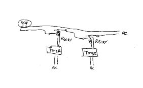
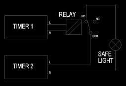
You need to use a relay for each timer and run the coils separately via each timer and the contacts (normally open) in series on the safelight power line. The safelight is plugged into it's own wall outlet and the safelight outlets on the timers power the relay coils. All power circuits are separate from each other and no chance of a short circuit.
I am not sure that is quite right. Could you explain in more detail so i [we] could be sure we understood correctly?
Steve