the maths for determining density range (with a scanner)

about to extinct

D
about to extinct

  • 0
  • 0
  • 0
Fantasyland!

D
Fantasyland!

  • 8
  • 2
  • 87
perfect cirkel

D
perfect cirkel

  • 2
  • 1
  • 119
Thomas J Walls cafe.

A
Thomas J Walls cafe.

  • 4
  • 6
  • 267

Recent Classifieds

Forum statistics

Threads
198,745
Messages
2,780,253
Members
99,692
Latest member
jglong
Recent bookmarks
0

pellicle

Member
Joined
May 25, 2006
Messages
1,175
Location
Finland
Format
4x5 Format
Hi

just going through some exersizes from "beyond the zone system" by Davis, and I was thinking about how to do the maths with numbers from my scanners "densitometer" setting. I was thinking that the specific scale of the numbers are after all unimportant only the linearity of the measurements is.

If I set the scanner to 'linear' and positive then I can get quick density readings by passing a 'magnifying glass' over the preview.

For example, looking at the 'thinnest' area of the negative I read a value of 218 and looking at the 'densest' area of the neg I get a value of 29.

So can I then calculate my density range as
log(218) - log(29) = 2.34 - 1.46 = 0.88

or should I do log(218 - 29) = log(189) = 2.26

or is none of this right?

BTW the film is ADOX sheet, and the image is a high contrast scene (a lamp with a visible bulb) in a darkened room.

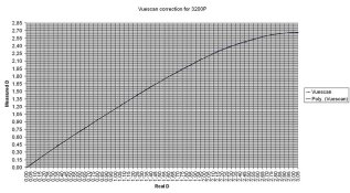
Sample of the linear scan with black points set

adox.jpg


Thanks for your time :smile:
 

Kirk Keyes

Member
Joined
Jun 17, 2004
Messages
3,234
Location
Portland, OR
Format
4x5 Format
I think you have the right idea, but you have to consider the gamma/slope/response of the scanner's detector. You're neg may have a density range of 2.26, but that's pretty high for most pictoral developing situations.

You need a calibrated negative so that you can scan that and then adjust the slope of the scanner.

Have you tried the Vuescan scanner software. I think it can give direct density readings. There was a trial download last time I looked at it.
 
OP
OP
pellicle

pellicle

Member
Joined
May 25, 2006
Messages
1,175
Location
Finland
Format
4x5 Format
Kirk

to address you questions, yes I'm comfortable that that the slope of the scan is linear (when setting this as linear in the software).

I know of and have used vuescan (considered again buying it) but find overall that the Epson scan (version 3.x) has enough functionality once you look around a bit. I prefer the simplicity of it (as I only want linear scans with black and white points based on my film base measurements) and find it hard to get used to vuescan's complexity (which perhaps I don't need).

I just wanted to confirm my maths ... I think its log (dark - light)

definately this is high for a 'pictorial scene' but I'm just testing my films limits ;-)

thank you for your advise
 

gainer

Subscriber
Joined
Sep 20, 2002
Messages
3,699
The gradient between two points on the H&D curve is (log of the higher - log of the lower) divided by (log of the higher exposure - log of the lower exposure). You left out the latter part. You have a pretty good measure of the density difference between light and dark, but did not account for the exposure ratio that caused it. Any gradient can, of course, produce both high and low densities depending on the scene brightness range, so simply measuring high and low densities does not tell all you need to know to calculate gradient. You can certainly compare the densities at the same points of two negatives of the same scene and determine which is higher in contrast, but you are not certain where these two points fall on a curve of gradient vs development time. If the points you measure are on a density step wedge, you have what you need by measuring the negative densities at the images of two known steps. If you have a step density wedge, or preferably one each transmissive and reflective, you can calibrate the scanner.
 

Usagi

Member
Joined
Apr 17, 2007
Messages
362
Location
Turku, Finla
Format
Multi Format
Gainier is right. You can use step tablet for calibration.
I use epson 3200 flatbet scanner with vuescan as an densitometer.

I simply scanned the stouffer step tablet and then checked what values vuescan's densitometer function gave. From these two values I created correction table and diagram.

As for epson 3200, the more density increases, the more epson's reading will be off.

The attachment has example of my correction curve. As you can see, scanner's output is far from linear.

The y-axis is density that scanner gives and x-axis has corrected density.
 

Attachments

  • Epson3200_density.jpg
    Epson3200_density.jpg
    168.3 KB · Views: 195
OP
OP
pellicle

pellicle

Member
Joined
May 25, 2006
Messages
1,175
Location
Finland
Format
4x5 Format
Hi

konnichiwa usagi-sama, gokuro sama deshita ...
doumo arigatou gozaimashita. Sumimasen deskedou, mou sukoshi shitsumon arimasu, .


interesting, thank you for posting that data.

I use epson 3200 flatbet scanner with vuescan as an densitometer.

I simply scanned the stouffer step tablet and then checked what values vuescan's densitometer function gave. From these two values I created correction table and diagram.

Firstly, I assume that you did not have any applied gamma in the vuescan operation.

Was any area more or less linear (if the actual data was there on the graph as well as the trend line it would be valuable too).

I understand that all instruments require calibration (including any calibration reference instruments), so I am hardly surprised that a non scientific consumer oriented instrument is 'out'

I simply scanned the stouffer step tablet and then checked what values vuescan's densitometer function gave. From these two values I created correction table and diagram.

There seems more data points than the amount for a stouffer step tablet, I assumed that your software 'smoothed' the curve as the appearance of Poly suggests as a data set in the graph and that sample data is not presented. How did you determine the (apparently log) values for the scanner output data?

As for epson 3200, the more density increases, the more epson's reading will be off.

The attachment has example of my correction curve. As you can see, scanner's output is far from linear.

so was this reflectance density (effectively measuring the print) or transmission density (measuring the negative)?

thanks for your time.

btw, I visited your gallery, and I liked your many images of Japan. I would be interested to know if you were using 120 roll type cameras or sheet film camera?

:smile:
 
Joined
Dec 30, 2005
Messages
7,175
Location
Milton, DE USA
Format
Analog
Wouldn't 2.26 be just a hair over a 7 stop range (2.1)? If the math is applicable, I wouldn't think that just of seven stop with B&W negative films would be totally without the realm of reality. I guess one way would be to scan a zone system gray chart, make sure Zone 0 values near 0 and that Zone X is near 255.
 
OP
OP
pellicle

pellicle

Member
Joined
May 25, 2006
Messages
1,175
Location
Finland
Format
4x5 Format
Christopher

I'm not sure, but I understood that this was the density range of the film, not the density range of the scene.

Anyway, I've since bought a Stouffer stepwedge myself, and found that results were quite similar to those of Usagi. Here is what I got from my machine

00Ovm9-42529484.jpg


In my procedure I also did a small experiment where I covered the calibration area of the scanner to try to bring the white point up. I found that it did bring this up. I think that its more or less a linear responce right up to about the 18th step of the wedge (more or less a 9 stop range if I understand things.

I think this makes the unit quite a good tool, both as a densitometer for my film and a reflectance meter for my print making too!

hope this helps other out there
 
Photrio.com contains affiliate links to products. We may receive a commission for purchases made through these links.
To read our full affiliate disclosure statement please click Here.

PHOTRIO PARTNERS EQUALLY FUNDING OUR COMMUNITY:


Ilford ADOX Freestyle Photographic Stearman Press Weldon Color Lab Blue Moon Camera & Machine
Top Bottom