• Welcome to Photrio!
    Registration is fast and free. Join today to unlock search, see fewer ads, and access all forum features.
    Click here to sign up

Spectrosensitometer

Somewhere...

D
Somewhere...

  • 2
  • 1
  • 42
Iriana

H
Iriana

  • 5
  • 1
  • 91

Forum statistics

Threads
202,735
Messages
2,844,845
Members
101,492
Latest member
code0312
Recent bookmarks
2
Okay! How about this;

I ordered some surface-mount LEDs from Ebay/China, the wavelengths I am missing. Unfortunately, they always sell at least 10 to 20 pieces, whereas I only need one of each :wink:. And I have hundreds or thousands of some wavelengths already.

I happen to make PCB's all the time and it would be wasteful to make just one of those tiny little boards. So, I will make several of them at the same time. And once I need to calibrate mine, I can just apply that calibration to all of them. I am thinking about fixed resistors.

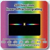
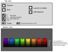
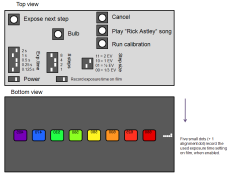
So, those will be tiny little units with a series of LED's: for example, IIRC, 660, 625, 600, 580, 550, 520, 470, 400 nm. As they are LED's, they are not sharp but show some response to +/- 25 nm so there is a bit uncertainty there, and the calibration won't be perfect either, but at least it will be cheap, small (something like a credit card) and simple and quickly done. It will need some kind of diffusor, but I have a solution for that ready too. It will work from a 9V battery and cost something like 5-10 USD.

I can include a simple timer to the design with practically no extra size or cost.

Anyone interested? What about the dimensions? I was thinking the LED "bar" could be something like 5 cm (2") long.

I will build this one for myself anyway and this is easy to "mass produce" in a range of 1-10 units.
 
hrst,
Yes , for such a price, or a little more, I am absolutely interested. Anything I do not have to build myself. I have built things from wood, glass and plastic. But never anything involving wires and solder.
Bill
 
hrst,

Maybe you could stack them in a grid... 10 LED's of each frequency for example. Use fixed resistors to attenuate each LED a little more than the one above to it to create a wedge of that part of the spectrum. Then maybe with a dozen stacks like this...

Use a few more components this way. But you wouldn't have to place it on a dozen Stouffer scales.
 
Bill;

If you turn the wedge 90 degrees, you only need one step wedge. It has to be wide enough for the entire spectrum though.

PE
 
hrst, I would definitely love to get my hands on such a gizmo. Looking at your past electronics skills, I have no doubt you can make one! Nevermind my previous neigh-saying... :whistling:

Ok, so attached is a depiction of a typical step wedge like we all use (Stouffer), and then an ideal form for a spectrosensitometer. We need something that's more "squat". Hamburger as opposed to hotdog... if you will. Right?

Now why is a thin slit so important? That spectroscope article suggests that it should be 2-10 mils wide. Why does the light have to be collimated exactly?

I've found 500 lp/mm and 1000 lp/mm diffraction gratings on eBay for very cheap; like the attached image. I think I'm going to just have to buy these and play around with them to see how they act in different circumstances. Again, in every diagram the diffraction grating or the focusing lens is oriented at an angle; is this the only way to get the diffraction grating to "do its stuff"?, that is, to spread out an image of the spectrum.

It'd be ideal to use plastic lenses so that we don't alter our UV transmission much. Cheap acrylic lenses abound, in all different types of powers.
 

Attachments

  • step wedges.JPG
    step wedges.JPG
    19.7 KB · Views: 174
  • diffractiong rating.JPG
    diffractiong rating.JPG
    21.9 KB · Views: 164
What we need is the step wedge on the right and a grating that produces an "image" as high as the step wedge. In simpler terms, the wedge should be about 4x5 and the grating should supply uniform illumination over that area. Otherwise, the result will be useless. Stouffer Iand EK) made wedges with different size steps and in different size sheets. Kodak sheets were up to 8x10, and the smallest step was 0.3 inches (IIRC). Steps were in 0.15, 0.3 or 0.6 increments.

PE
 
So projecting a nice, big and evenly illuminated spectrum is the crucial thing here.
 
Wouldn't one with reduced number of steps still be quite useful? Even with just one mid-density, we could measure the relative sensitivities. AFAIK, there should be no contrast difference between wavelengths in a BW material, so density difference at mid-density should be directly comparable to shadow speed at that wavelength. That being said, of course a step wedge helps to find the speed directly without using a densitometer (or scanner).

I actually was thinking about this project two years ago and have a prism for this purpose. But I think that with a prism, there is a risk of unwanted reflections in the prism itself and in the optical system, too, risking some white light leak-through which would be detrimental for the measurement. I suppose that the diffraction grating has smaller risk if done right, but it is hard verify by eye that you are not having any leak. You should have a sharp-cutting red, green or blue filter and place that filter on a region with supposedly no such wavelength to verify that. So, I'm going the LED way first just because it's so simple; but I'm going to make it small. Maybe I can fit 4-5 steps.
 
You may have a situation where you did not add enough dye. With a limited scale, you would not see the tiny bump of the sensitivity region with that tiny amount of dye added. So, we used a big scale relatively speaking.

And, a variation in contrast as a function of wavelength is not unusual. After all, you are using white light for exposure and the curve is the integral of all wavelengths but with a spectrosensitometer you actually can see these variations.

PE
 
OK, I was thinking something like this. Any comments appreciated!

For situations where more steps are needed, 2 or more subsequent exposures with different exposure times could be used side-to-side.
 

Attachments

  • spectro.png
    spectro.png
    40.8 KB · Views: 197
Last edited by a moderator:
The exposure timer and the time recorder are really awesome; great ideas!

You mentioned a diffuser, and will this be integrated with a step wedge?

Presumably the LED will be in a cavity of sorts, and the diffuser placed some distance away; perhaps along the bottom surface where it will make contact with the test film? The "cells" will have to be isolated well of course, to prevent any cross-talk between spectral regions.

Honestly, it's a brilliant little device you're dreaming up here... LEDs open up so many possibilities.
 
OK, I was thinking something like this. Any comments appreciated!

For situations where more steps are needed, 2 or more subsequent exposures with different exposure times could be used side-to-side.

The scales you show are just fine. You must remember that for negatives you must go from Dmin to Dmax. This, of course, is the raw form of the emulsion.

If you do not go to Dmax, then you can miss the true extent of sensitivity.

What you show appears to be a reversal scale.

PE
 
Presumably the LED will be in a cavity of sorts, and the diffuser placed some distance away; perhaps along the bottom surface where it will make contact with the test film? The "cells" will have to be isolated well of course, to prevent any cross-talk between spectral regions.

Yeah, you got the details perfectly right! Then, the step wedge will be mounted to the diffuser and the step wedge is in direct contact with the film being exposed.

I'm probably just going to print custom step wedges. Those digital photography people who also occupy our club darkroom, have bought there a $2000 pigment inkjet that is GREAT for printing everything except photographs; for example, PCB exposure masks. I measured a Dmax of 2.8 when printed on a OHP film, and when printed at 1200 dpi, pixels can be seen with a microscope, so this is a great tool for making good enough custom step wedges. (Naturally, a spectral response of the black pigment ink is not guaranteed to be perfectly even, unlike those high-quality and expensive step wedges.)
 
More ideas:

Making it smaller, simpler & cheaper by leaving out the step wedge (or multiple leds) completely and making the LED spots smaller, and make it blink N times with increasing exposure, so that you move it along the material and get a step wedge-like exposure.
 
Like this.......
 

Attachments

  • spectro_v2.png
    spectro_v2.png
    43.1 KB · Views: 181
I think a step wedge is important. Any kind of "dynamic" exposure (where it has to be moved manually) is going to be really troublesome methinks. It's going to destroy the whole continuity of having an identical-looking pattern that can be easily compared to others at a glance.

I also think you should consider switching from a Rick Astley song to, say, an Oingo Boingo song. Thoughts?
 
I think holmburgers is right moving the device would be hard, and make it less reliable.

But I agree with PE, if I understand the idea, a grid pattern to outline where you are looking sounds like a good idea.

I still like the fixed resistors to calibrate and multiple LED's of each wavelength idea. If necessary you could make different ones blink a specific number of times but there would be intermittency effects.

How about, keeping it credit card size but spread the small spots out so they are unlikely to interfere with each other. At regular intervals place a white LED to provide a benchmark grid.

Might as well add a "white" LED column as well to provide for exposure test - even if it is not sensitometrically perfect light it may add to the usefulness.

As PE said, you really need to go to DMax so 10 full stops of exposure range from dimmest to brightest (or shortest to longest exposure).

I am intrigued by the possibility it can be done without a Stouffer scale, with the LED's in direct contact with the emulsion. Then you don't have to make a diffusion chamber or other manufacturing invention. It can be a bare surface mount electronic device with one part and a battery. I almost want to recommend using a "123" battery. They are not uncommon these days and provide a good amount of 3v power.
 
Bill;

There were small desktop spectrosensitometers all over Kodak Park at one time, along with the big units for precise work in B-30 and B-57 for film and paper. IDK what happened to them. Results using them are found in Haist, Mees and also in my book.

PE
 
Now, Kirk, you say you have a spherical mirror with a grating in it; how would that design work? It sounds like that would be fundamentally different from the above diagram posted by Emulsion.

Sorry for taking so long to get back - I'll had a bad cold the last week...

Yes, a spectrometer with a mirror (by using a reflection grating) does have quite a bit different layout than one that uses a transmission grating. The reflection gratings, both flat and with curvature, make spectrometers that can be more compact then transmittion gratings as the light path can fold back over itself.

The reason I found a spherical reflection grating is that I was going for a design that's called a "Rowland circle spectrograph". With a Rowland circle spectrograph, if the inlet slit and the grating all lie on a circle, then the diffracted spectrum will also lie on the same circle. The diameter of the circle equals the radius of curvature of the grating blank. So if the circle is large, then you can make a pretty big spectrogram with no extra lenses or mirrors.
See:
http://gratings.newport.com/library/technotes/technote3.asp

The drawback is that if you have to use film to measure the spectrum, then you need film that's on a flexible support, like paper or acetate. I was looking at testing variable contrast papers at the time that I bought the mirror, so that would not have been an issue. Glass plates would have been a bit of a problem...

I also bought a flat relection grating as well, just for fun and in case I wanted to use plates.

I was going to use colored LEDs as a way to light sources to calibrate my spectrograph, but I like the idea of using LEDS at various wavelengths to make "spot tests" at those wavelenghts by contacting emulsions directly on the LEDs. I like the idea of making an array - "columns" of various wavelengths and then "rows" at differing light intensities.

One thing to think about is that LEDs can have fairly wide emission spectra - some designs like "superirradiant" LEDs are a bit more like LASER diodes and have more narrow spectra emision.

Side note, my second year physics professor at Reed College in 1983 told that class that if any of us figured out how to make a commercially viable blue LED, we would be rich! Too bad I dropped out of that class before I had a clue about how to make a blue led... (Well, I knew, you had to make a diode with a higher energy gap). Now I see that someone started selling blue LEDs in 1989.
 
Some talk and inklings of a DIY spectrosensitometer from 5 years ago; did anyone ever get around to doing it?

Still on my list to do someday...


So let's break down what the optical path might look like. It's hard to tell from the diagrams what exactly is happening in the 3rd dimension.

The image of the slit continues on through the spectrometer unless it gets blocked out. So the projected image with the spectrum will be as tall as the slit.


So we have a light source and a lens (simple meniscus?) to concentrate the light onto a slit. The slit will presumably create a thin "bar" of light that next must go to a diffraction grating. I think the "science class" type gratings that are mounted in 35mm slides would be ideal, as has been noted above.

Those cheap, 35 mm slide diffration gratings are typically not very efficient. A "replica" grating is going to be a better solution than the cheap holographic ones. Best are original or master ruled gratings, but who can afford those?

Now, does the angle of the grating affect how the light is diffracted, and how much it fans out?

Yes, the ruling angle controls the angle of diffration, The more lines per inch or mm controls the range of wavelengths that can practically be diffrated. Replica gratings will have the same diffration angle as the ruled grating that they were copied from.


How important is the collimator in front of the grating? It looks like the purpose of that is to get the light to come at it perfectly parallel. But wouldn't a horizontal bar of light (from the slit) hitting the grating still make a reasonable projection of the spectrum?

Collimated light will give a sharper image of the spectra. If you have your light source a LONG ways away relative to the dimensions of your spectrograph, then you would not need a collimator. If your light blulb is right next to close to the slit, then you will definitely want to collimate the light source.


What I'm having trouble imagining is the interaction between the projected spectrum and the step wedge. Most step wedges that we know are arranged in a long thin strip, not wider than a centimeter or two. How on earth are we supposed to project the spectrum onto this and achieve a 21-step gradation at all spectral frequencies? We need each spectral region (400, 500, 600, etc.) to go through the whole range of steps. This seems obviously impossible with the thin step wedges that we're all used to.

As I said above, the image of the slit will project though the spectrometer unless it is blocked by something. It's hard and expensive to get gratings of any great width, so you want to maximize what you have going through the spec.

I was planning on getting a centimeter or two at the most of spectra. So I was going to make multiple exposures on the film/paper at various light intensities to get the spectral info for the film. To change the intensity, I was planning on keeping the exposure time at 1 second, and then using Wratten ND filters between the light source and the slit. Since I can measure the spectral characteristics of the Wratten ND gelatin filters with a spectrometer that I have (or look them up online as Wratten/Kodak publishes this info) then I could apply a correction to my measured spectrograms.

Scan through this book - it's pretty good and has all the math and more that you'd need to calculate anything with gratings.
http://gratings.newport.com/library/handbook/toc.asp
 
Bud good, durable blue LEDs just recently (Blue Ray).

Blu-Rays use LASER diodes at 405 nm - funny thing is that is considered a "violet" wavelength!

I see Sony unvieled a Blu-Ray prototype in Oct. 2000 - I'm not sure when the diodes were invented, but it's certainly a few years before they showed the Blu-Ray.

Speaking of random LASER devices, here's something I plan on making some day - a Laser Harp:
http://youtu.be/sLVXmsbVwUs

I love when the laser fans out after first being powered up!
 
That harp reminds me of the sound track from Forbidden Planet! :wink:

Actually, I knew of the difference between the blue LED and the blue Laser, but they were both slow coming to fruition due to longevity issues and other problems.

PE
 
Yes, a spectrometer with a mirror (by using a reflection grating) does have quite a bit different layout than one that uses a transmission grating. The reflection gratings, both flat and with curvature, make spectrometers that can be more compact then transmittion gratings as the light path can fold back over itself.

I see. In that case you could optically contact (index match) a transmission grating to a mirror.

By the way, what about simply use a CD, DVD, Bluray disc as a grating, wouldn't that be an option?


One thing to think about is that LEDs can have fairly wide emission spectra - some designs like "superirradiant" LEDs are a bit more like LASER diodes and have more narrow spectra emision.

Yes. In my opinion LEDs are probably too much broadband for such an application. Lasers might be far better for "callibration". Lasers at 405, 445, 532 and 650 nm have become very affordable...
 
Yes, the ruling angle controls the angle of diffration, The more lines per inch or mm controls the range of wavelengths that can practically be diffrated. Replica gratings will have the same diffration angle as the ruled grating that they were copied from.

Speaking in "holographics" the number of lines per mm is called spatial resolution. The higher the resolution the larger the angle between the input and the output (the diffracted) beam.
 
Photrio.com contains affiliate links to products. We may receive a commission for purchases made through these links.
To read our full affiliate disclosure statement please click Here.

PHOTRIO PARTNERS EQUALLY FUNDING OUR COMMUNITY:


Ilford ADOX Freestyle Photographic Stearman Press Weldon Color Lab Blue Moon Camera & Machine
Top Bottom