Shutter Speed Testing and measurements

Tyndall Bruce

A
Tyndall Bruce

  • 0
  • 0
  • 15
TEXTURES

A
TEXTURES

  • 3
  • 0
  • 42
Small Craft Club

A
Small Craft Club

  • 2
  • 0
  • 43
RED FILTER

A
RED FILTER

  • 1
  • 0
  • 34
The Small Craft Club

A
The Small Craft Club

  • 3
  • 0
  • 38

Recent Classifieds

Forum statistics

Threads
198,900
Messages
2,782,732
Members
99,741
Latest member
likes_life
Recent bookmarks
0

bergytone

Member
Joined
Sep 8, 2014
Messages
168
Location
Grand Haven,
Format
Multi Format
Hello all,
I know what you're thinking... not another thread about Shutter speed testing. What I'm working on is I'd like to make a handheld shutter tester, similar to the Calumet tester, but maybe a little more up to date and higher tech with an LCD screen. If all goes well, I would like to package it up for sale to the masses. I have lots of experience building electronic items to sell outright, so I'm not afraid to put this together.

I looked through the posts on shutter speed testing, and there seems to be a couple prominent testing methods out there. One uses a video monitor to capture video frames and the other is the popular phototransistor plugged into Audacity. My post is not to debate which of these methods work better, but to share some of my observations on the bench regarding optically measuring shutters.

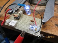
I have lots of data, and I don't want this to be the longest post in history, so I'll break it into pieces. First, I'll describe the setup. First I built up a receiver with a very accurate photodiode/ amplifier part offered by TI. To verify the speed of the receiver, I also built an LED driver with variable duty cycle (on time) so I could test my detector's speed accuracy.

attachment.php


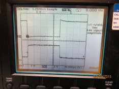
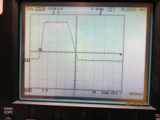
You can see the LED hovering over the detector in the lower right corner of the board. I set the LED to pulse at 1ms, which is 1/1000 sec. Here is an oscilloscope plot of the signals going in and coming out:

attachment.php


Explanation: the upper waveform shows the voltage driving the LED (light source) and the lower waveform shows the output of the detector. If you're not a techhie, I apologize, but this is how we electrically check the capability of the detector. You can see that the two waveforms are the same width, even though one is inverted. I ran a few more tests at higher speed and found that the detector follows the LED signal to within 5 microseconds, which is better than I thought it would be. It means that the detector has an error of 5/100,000 of a second. Great. I found out also that if the detector is blasted with a lot of light and it 'saturates'. the error grows to over 20 microseconds, but if the device is kept within its 'linear region.

So onward to trying to test a shutter speed.
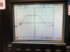
I set up my light source (an LED flashlight) in front of my Nikon FM and the detector right behind the shutter curtain. I set the speed to 1/125 sec and here's the waveform of the light coming through:
attachment.php


If you notice, the scale of the waveform is 2 milliseconds per division. 1/125 is 8 milliseconds. The width of this pulse is approximately 8 ms. If you look at the point where the waveform starts and stops, it is 9ms. If you look at the top portion of the waveform it measures a true 8 milliseconds.

The slope of the rising edge and of the falling is is pretty pronounced. It's nearly a millisecond. I feel this is probably due to the 'prenumbra' effect of the shutter. One would expect a sharp rise and fall time, but because this effect, there is a shadowing effect of light that gets around the shutter as it moves.

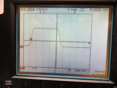
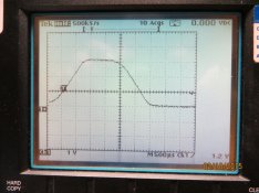
This effect starts to get more of an issue with higher shutter speeds. Here's a plot of a 1/500th shutter setting on the Nikon. I took the lens off to see if it made any difference, and it didn't:
attachment.php


1/500 sec should measure out to 2 milliseconds. Looking at the waveform, note that the scale is now 500 microseconds per division. The measurement at the lowest part of waveform is 4 milliseconds wide, and about 1 1/2 millseconds wide at the top. So my question is....
how would interpret this speed and display it on a shutter tester LCD?

It even gets harder to quantify at the 1/1000 setting. At this point I'm going to open it up for discussion. I have a bunch of other waveforms to post, but as I said I don't want this to be the longest post in history. Some of the old leaf shutter cameras I tested had extremely long rise and fall times. I thought of posting this in the DIY/ electronics group, but groups don't seem to get the coverage that general posts do.
 

Attachments

  • setup 1.jpg
    setup 1.jpg
    273.6 KB · Views: 429
  • calibration 1ms.JPG
    calibration 1ms.JPG
    337.3 KB · Views: 456
  • Nikon 125th.JPG
    Nikon 125th.JPG
    322.8 KB · Views: 417
  • Nikon again 500th no lens.JPG
    Nikon again 500th no lens.JPG
    328.1 KB · Views: 424

John Koehrer

Subscriber
Joined
Apr 3, 2004
Messages
8,277
Location
Aurora, Il
Format
Multi Format
FWIW, there's a seller on e bite, vfmoto that's made something similar and has been pretty popular.
He's got a couple, LED or LCD display, with or without light source or power supply.

Doesn't help with the question though, sorry.
 
OP
OP
bergytone

bergytone

Member
Joined
Sep 8, 2014
Messages
168
Location
Grand Haven,
Format
Multi Format
John, I did see those... he's in Romania. It looks like a good box. I'd like to do something similar, just not for $130 plus $25 shipping.. He has sold about 25 according to his feedback.
 

Carriage

Member
Joined
Feb 3, 2015
Messages
219
Location
Melbourne
Format
35mm
How well does it match if you weight by % open? Like, normalise so that fully open is 1 and closed is 0, then integrate to get the opening time. If exposure is illuminance by time, this would be more representative, yeah?
 

Carriage

Member
Joined
Feb 3, 2015
Messages
219
Location
Melbourne
Format
35mm
If you assume the shape is trapezoidal, so ignoring the curves in the transitions, taking the average of the two values would be the same thing I believe.
 

480sparky

Member
Joined
Nov 28, 2014
Messages
602
Location
Corn Patch USA
Format
Multi Format
I wonder if anyone has the schematic for my timer:

NortheastInstrumentsShutterTimer.jpg
 
OP
OP
bergytone

bergytone

Member
Joined
Sep 8, 2014
Messages
168
Location
Grand Haven,
Format
Multi Format
Carriage, I think the area under the curve makes sense. But to do this would require some serious sampling and integration of the samples to derive this. What I'm starting to think makes sense is to use the time average of the two values makes sense, and actually correlates pretty well with a lot of the different shutters I looked at. I will post more of the data and waveforms tomorrow... it's getting late!

480sparky, I'd love to see a schematic of that device if anyone has it... it looks pretty old, and with today's small micro controllers with pretty fast in-built A/D converters and DSP capability, there's a lot that one can do with the signals coming from the sensor. My guess is that your device just times the pulses coming from the sensor much like the simple $10 sensors that hook into the audacity audio program do.
 

Jim Jones

Subscriber
Joined
Jan 16, 2006
Messages
3,740
Location
Chillicothe MO
Format
Multi Format
Charging a capacitor and integrating the area under the curve was the easy way of doing it in the days of vacuum tube analog equipment. We've made some things more difficult by trying to make them newer and better. Integrating the area under the curve becomes even more desirable when checking the top speeds of between-the-lens shutters with their relatively slower opening and closing. Those top speeds should be checked at the aperture used for photography. Checking them at the widest aperture erroneously suggests slower speeds.
 

480sparky

Member
Joined
Nov 28, 2014
Messages
602
Location
Corn Patch USA
Format
Multi Format
.........480sparky, I'd love to see a schematic of that device if anyone has it... it looks pretty old, and with today's small micro controllers with pretty fast in-built A/D converters and DSP capability, there's a lot that one can do with the signals coming from the sensor. My guess is that your device just times the pulses coming from the sensor much like the simple $10 sensors that hook into the audacity audio program do.

This one uses a photocell. I bought it back in the early 80's. Not many were made, but I do remember seeing someone post the schematic online when I did a search a few years ago. Sadly, I can't find it any more.

But for your viewing pleasure, I took the back off so you could take a peek under the hood:

Timer1.jpg


Timer3.jpg


Timer2.jpg


I'm not much into electronics, so I don't have the ability to reverse engineer this. But maybe someone else can.
 

Jeff Bradford

Member
Joined
Jan 14, 2015
Messages
421
Location
Rolling Prairie, IN
Format
Medium Format
That's a pretty simple circuit. With a clear photo of the printed side of the circuit board, the schematic could be redrawn. Its good-old TTL logic.
 

DWThomas

Subscriber
Joined
Jun 13, 2006
Messages
4,605
Location
SE Pennsylvania
Format
Multi Format
That's a pretty simple circuit. With a clear photo of the printed side of the circuit board, the schematic could be redrawn. Its good-old TTL logic.

Yes! A single-sided circuit board and discrete components -- don't see that much any more -- he says wistfully! :cool: The main problem might be identifying or finding enough info on some of the semiconductors to find them or their equivalents. Some commercially made stuff used custom marked parts just to frustrate reverse engineering by the competition. Of course it may well be once a schematic is in hand the design will be obvious enough to do any minor "re-engineering" as needed.
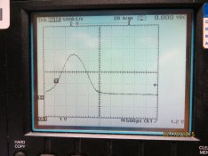
 
OP
OP
bergytone

bergytone

Member
Joined
Sep 8, 2014
Messages
168
Location
Grand Haven,
Format
Multi Format
Thanks Sparky, that helps. This is a very simple system using a gated counter. The top two ICs are LED display drivers, the two ICs under them are 3 digit BCD (binary coded decimal) counters probably set as up counters. The main IC that does the detection is an LM339 quad comparator. I'm sure they use 1/4 of it to create a threshold for the counter to start, then another section set up as a free running oscillator to make pulses to count, and the last stage as some kind of gate to let pulses through to the counter. My guess is that they are running the oscillator to generate pulses at 1 microsecond rate, and then when the voltage from the photo-detector reaches a set threshold it starts the counter. Once the signal comes back down , it stops the counter.

This technique is pretty straightforward and simple. The key to it's accuracy is how they picked that threshold. This goes back to my original quest.... how do you interpret the waveform...

Here's the waveform of the Nikon FM set to 1/1000. You can see it never really tops out... it doesn't achieve a flat top.

attachment.php


1/1000 should have a duration of 1 millisecond, or two divisions of the display above. The lower part of the waveform is about 3 1/2 divisions. Two divisions occurs at about 2/3 up the waveform. It kind of goes back to the average area under this curve. Since I'm already getting overly technical... I starting to wonder if taking the RMS (root mean square) value of this waveform would derive the proper 'threshold' or timing points.

As jim Jones said previously, sometimes simple is best. The circuit used in 480sparky's northeast tester is as simple as it gets and depending on how they set the threshold, may be pretty accurate. for shutter speeds lower than say 1/250 it is probably dead on.

Here's another camera.. a 30's Voightlander Bessa folder. The shutter was set to 1/100. Look at how slow the shutter closes. It takes nearly 2 milliseconds to close. (2 milliseconds per every division) Again, determining the actual shutter speed is a matter of interpretation of this waveform.

attachment.php
 

Attachments

  • Nikon again 1000th no lens.JPG
    Nikon again 1000th no lens.JPG
    333 KB · Views: 269
  • Voightlander Bessa 100th.JPG
    Voightlander Bessa 100th.JPG
    314.2 KB · Views: 300
OP
OP
bergytone

bergytone

Member
Joined
Sep 8, 2014
Messages
168
Location
Grand Haven,
Format
Multi Format
DW, I noticed the single sided PCB too. It almost looks like a prototype, as it has hand written things on it. If I had to guess, the Calumet shutter tester is probably almost identical to this. If anyone has a Calumet tester that they'd be willing to take the back off, I'd love to see the guts of it.
 

DWThomas

Subscriber
Joined
Jun 13, 2006
Messages
4,605
Location
SE Pennsylvania
Format
Multi Format
My aging brain seems to recall most pulse width measurements were made at the 50% point. If the bandwidth and signal range is such that the waveform is a nice trapezoid, that's seems a reasonable thing to do. If it reduces to a wobbly bump, maybe less so. In the waveform you show at 1/1000, I wonder if the mushy waveform is truly the shutter performance or some lag in response of the photo sensor or other circuitry, in which case it should be possible to do better.
 

480sparky

Member
Joined
Nov 28, 2014
Messages
602
Location
Corn Patch USA
Format
Multi Format
Thanks Sparky, that helps. This is a very simple system using a gated counter. The top two ICs are LED display drivers, the two ICs under them are 3 digit BCD (binary coded decimal) counters probably set as up counters. The main IC that does the detection is an LM339 quad comparator. I'm sure they use 1/4 of it to create a threshold for the counter to start, then another section set up as a free running oscillator to make pulses to count, and the last stage as some kind of gate to let pulses through to the counter. My guess is that they are running the oscillator to generate pulses at 1 microsecond rate, and then when the voltage from the photo-detector reaches a set threshold it starts the counter. Once the signal comes back down , it stops the counter..........


All Greek to me!

All I know is that it seems to be fairly accurate, in terms of shutter speeds in practical use. I've used this on both my film and digital cameras, and where my film shutters are measured to be off, exposure in the field verify it. That's the only accuracy I'm concerned with.
 

Laurent

Subscriber
Joined
Oct 15, 2004
Messages
1,829
Location
France
Format
Multi Format
Thanks Sparky, that helps. This is a very simple system using a gated counter. The top two ICs are LED display drivers, the two ICs under them are 3 digit BCD (binary coded decimal) counters probably set as up counters. The main IC that does the detection is an LM339 quad comparator. I'm sure they use 1/4 of it to create a threshold for the counter to start, then another section set up as a free running oscillator to make pulses to count, and the last stage as some kind of gate to let pulses through to the counter. My guess is that they are running the oscillator to generate pulses at 1 microsecond rate, and then when the voltage from the photo-detector reaches a set threshold it starts the counter. Once the signal comes back down , it stops the counter.

This technique is pretty straightforward and simple. The key to it's accuracy is how they picked that threshold. This goes back to my original quest.... how do you interpret the waveform...

Here's the waveform of the Nikon FM set to 1/1000. You can see it never really tops out... it doesn't achieve a flat top.

attachment.php


1/1000 should have a duration of 1 millisecond, or two divisions of the display above. The lower part of the waveform is about 3 1/2 divisions. Two divisions occurs at about 2/3 up the waveform. It kind of goes back to the average area under this curve. Since I'm already getting overly technical... I starting to wonder if taking the RMS (root mean square) value of this waveform would derive the proper 'threshold' or timing points.

As jim Jones said previously, sometimes simple is best. The circuit used in 480sparky's northeast tester is as simple as it gets and depending on how they set the threshold, may be pretty accurate. for shutter speeds lower than say 1/250 it is probably dead on.

Here's another camera.. a 30's Voightlander Bessa folder. The shutter was set to 1/100. Look at how slow the shutter closes. It takes nearly 2 milliseconds to close. (2 milliseconds per every division) Again, determining the actual shutter speed is a matter of interpretation of this waveform.

attachment.php

Concerning the FM, the first thing thatcame to my mind is that the measurement gets some parasit light, as for speeds above the sync speed, the shutter opening is a slit. SO I guess for these shutters, I think you need to make your detection more "directional" so that the light does not reach the sensor when the slit is not rightin front of it.

It may even be that the detector is too large, no ?
 

Chan Tran

Subscriber
Joined
May 10, 2006
Messages
6,821
Location
Sachse, TX
Format
35mm
You would need a sensor which has much narrower angle of acceptance. The trapezoid that you see because when the shutter partly cover the sensor it still has output. However if you could build a tester like the Kyoritsu EF-8000 and selling it for about $1000 I would be interested.
 
OP
OP
bergytone

bergytone

Member
Joined
Sep 8, 2014
Messages
168
Location
Grand Haven,
Format
Multi Format
DW, if you look at my first post, I wanted to show that the detector I'm using is capable of tracking an LED light source that flashes at just a few microsecond rate. So I'm pretty confident that there's no lag in the detector.

sparky, you are right... all that matters is that it gives meaningful numbers that you can use to adjust exposures. Can you briefly tell me how you work it? Do they recommend a certain light source? Or do you just point it at a lamp?

A tester like Sparky's could be replicated and built very cost effectively. I'm hoping there's a market out there for one, since these are no longer available....
 

480sparky

Member
Joined
Nov 28, 2014
Messages
602
Location
Corn Patch USA
Format
Multi Format
.....sparky, you are right... all that matters is that it gives meaningful numbers that you can use to adjust exposures. Can you briefly tell me how you work it? Do they recommend a certain light source? Or do you just point it at a lamp?........

For film, I just remove the back of the camera and hold the photocell behind the shutter. With a lamp on the other side that's bright enough to trigger it, that's all that's needed.

For my DSLRs, I rig up a laser and bounce it off the AA filter into the photocell.
 
OP
OP
bergytone

bergytone

Member
Joined
Sep 8, 2014
Messages
168
Location
Grand Haven,
Format
Multi Format
Chan Tran, I'm glad you brought this up. If you want to precisely measure the speed of the curtains, you need to have a pinpoint sensor. But film in the camera is not a pinpoint. I would think in all reality, you'd want a sensor as big as the film to get a true average of the light hitting the film. But this is not practical. So the expensive device will give an absolute precise time that the curtain is open, but is that a true representation of the light hitting the film? I would think for it to work properly, the sensor must be almost touching the shutter. Do you agree?
 

DWThomas

Subscriber
Joined
Jun 13, 2006
Messages
4,605
Location
SE Pennsylvania
Format
Multi Format
. . . I would think in all reality, you'd want a sensor as big as the film to get a true average of the light hitting the film.

My gut feeling on this is no; the sensor needs to be equal or smaller than the narrowest slit in a focal plane. A film sized sensor would show some average value during the whole motion of the slit which would not be the average exposure. Of course, I suppose one could go to some analog process and evaluate the area under an analog curve and .... [oh no-o-o, I'm supposed to be working on an art club newsletter that's already late ..... :w00t:]
 

DWThomas

Subscriber
Joined
Jun 13, 2006
Messages
4,605
Location
SE Pennsylvania
Format
Multi Format
DW, if you look at my first post, I wanted to show that the detector I'm using is capable of tracking an LED light source that flashes at just a few microsecond rate. So I'm pretty confident that there's no lag in the detector.

....

Whoops, yes, (can I plead short term memory failure?! :blink: )

Gulp, that may also argue for a more analog approach (which makes my brain hurt!) Of course, if that's all in the shutter mechanics, one may just say "it's an approximation" which seems generally agreed to be the case at the highest speed with most leaf shutters. I would expect a focal plane to be pretty accurate. But this also could get into "signal conditioning" issues (and thus that threshold, among other things).

Enh, open a half stop at the highest speed and shoot .... :whistling:
 
Last edited by a moderator:

E. von Hoegh

Member
Joined
Sep 14, 2011
Messages
6,197
Location
Adirondacks
Format
Multi Format
Chan Tran, I'm glad you brought this up. If you want to precisely measure the speed of the curtains, you need to have a pinpoint sensor. But film in the camera is not a pinpoint. I would think in all reality, you'd want a sensor as big as the film to get a true average of the light hitting the film. But this is not practical. So the expensive device will give an absolute precise time that the curtain is open, but is that a true representation of the light hitting the film? I would think for it to work properly, the sensor must be almost touching the shutter. Do you agree?

This is correct. I made a widget using a photodiode, it connects to an oscilloscope and I use it to time shutters. I don't use exactly a pinpoint, but a short tube with a tiny inner diameter, maybe .015. A simple circuit with a 1.5v battery, a 5k pot, and a small value capacitor, maybe 150pf across the output. The light makes the diode conduct and the voltage drop across a 5k pot is your pulse, the level is adjustable as the wiper arm is the output. Needs a bright lightsource, but it's dirt simple and works well
 
OP
OP
bergytone

bergytone

Member
Joined
Sep 8, 2014
Messages
168
Location
Grand Haven,
Format
Multi Format
Laurent, I may be coming around to your thinking. A very tiny detector would be similar to the grains of silver salt in the film. After all, that is what builds the image. One tradeoff with making the detector smaller and smaller is that it's sensitivity goes way down. The bigger the slice of silicon, the more sensitive it is, but the slower it is.

From a previous thread, I saw that someone put the photodiode back in a small tube, with a narrow aperature. Maybe that is a solution. A bigger photodiode for the sensitivity, but a narrow aperture to make it very directional.

That will be my next test tonight. I will post the results tomorrow.
For fun, here's what an argus "brick" C3 looks like at 1/100:

attachment.php


Very slow opening and closing. It is a continuously variable shutter speed, and the dial is pretty touchy. It also doesn't seem to have consistent results... each time it was slightly different, but not enough to have to change an F stop to compensate.
 

Attachments

  • Argus brick 100th.JPG
    Argus brick 100th.JPG
    329.9 KB · Views: 411

grahamp

Subscriber
Joined
Mar 2, 2004
Messages
1,706
Location
Vallejo (SF Bay Area)
Format
Multi Format
Focal plane shutters really need to be tested at the start, middle, and end of the run to make sure the curtains are traveling at a constant speed. I remember watching an Olympus technician working on one of my OM1s. That was done with the lens off and at three points. Mechanical focal plane shutters will likely be off at the top speed - 1/750 instead of 1/1000 is not unexpected. Electrically controlled shutters tend to be closer to specification.

I would have expected the sensor to be at the end of a tube to get a narrow angle of view. The geometry and calibration has to match what happens at the film plane, and with the camera back open you risk reflections.

Personally, I am not too worried about the actual speed of my shutters unless they have drifted a lot. I worry about inconsistency more.
 
Photrio.com contains affiliate links to products. We may receive a commission for purchases made through these links.
To read our full affiliate disclosure statement please click Here.

PHOTRIO PARTNERS EQUALLY FUNDING OUR COMMUNITY:


Ilford ADOX Freestyle Photographic Stearman Press Weldon Color Lab Blue Moon Camera & Machine
Top Bottom