Off topic technical question

Recent Classifieds

Forum statistics

Threads
199,129
Messages
2,786,680
Members
99,818
Latest member
stammu
Recent bookmarks
0

noacronym

Member
Joined
Mar 17, 2013
Messages
245
Format
Multi Format
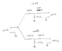
Thank you for allowing this post to remain. I have a technical question related to electronics and post it here because I think I know of a few folks who can answer me most correctly (insert my respect here). I would like to ask anyone who knows how to draw me up a little circuit to divide the signal from an HP 200 ABR into stereo so that I can run the signal into the inputs of tape recorders to align their circuits and heads. Typically, the line in would be 0db or .775 volts. But I do not know what kind of little resistor/capacitor arrangement I would need to fabricate. The HP ABR has a 600Ω output. I am providing a page from the manual. Thank you.The power output as listed in the HP 200 ABR manual is 1 watt or 24.5 V into a 600 ohm load
 

Attachments

  • question.jpg
    question.jpg
    819.9 KB · Views: 130
Last edited by a moderator:

tkamiya

Member
Joined
Oct 3, 2009
Messages
4,284
Location
Central Flor
Format
Multi Format
Hi,

If the source (your signal generator) can generate that much power, then I'd use something like 1:100 attenuator for 600 ohm unbalanced for L and R channels and tie the input side together. Attenuators will provide the necessary isolation as well as reducing the massive power into your equipment.

There is no need for capacitors as there is no DC components to block out.
 
OP
OP

noacronym

Member
Joined
Mar 17, 2013
Messages
245
Format
Multi Format
Thank you but I wouldn't know how to draw up such a schematic. I'm capable of reading schematics but not designing them.
 

tkamiya

Member
Joined
Oct 3, 2009
Messages
4,284
Location
Central Flor
Format
Multi Format
This is what I would do....

Each attenuator has an input impedance of 1200 ohm, output impedance of 600 ohm, and loss of -20db.
Since the input is in parallel, it will match the 600 ohm impedance of the source.

I found an online calculator for the resistor values.
 

Attachments

  • tkamiya007.jpg
    tkamiya007.jpg
    36.1 KB · Views: 127

tkamiya

Member
Joined
Oct 3, 2009
Messages
4,284
Location
Central Flor
Format
Multi Format
Oh, by the way, I would suggest using metal film type resistor. (see, it's FILM related!)
 
OP
OP

noacronym

Member
Joined
Mar 17, 2013
Messages
245
Format
Multi Format
Thanks friend. I'll whip up one of those that you just designed. Of course I'll have to go toRadio Shack, which doesn't sell electronics any more, and get the closest values I can and depend on the output control on the HP get my .775. I just didn't know how to split the signal and get all the impedences right. I knew the HP would overpower my tape recorder straight off the HP outputs. Looks like with your help I can move on to using this HP instead of generating my signals in Adobe Audition and taking my signals off the sound card. I still need to do some tests and make sure the HP is still putting out flat from 20-20,000. It might not. But if I can get it to generate my signals, I'll be happy. Still looking for a Leader LMV 181a or 185. Using a digital multimeter to calibrate my scope for converting db's to millivolts is a real pain. Thank you sincerely, again.--HTF
 
OP
OP

noacronym

Member
Joined
Mar 17, 2013
Messages
245
Format
Multi Format
By the way all this most certainly is related to photography. If you are listening to music while doing darkroom work, it's incorrect darkroom procedure if it isn't originating from a reel to reel tape deck. Just not done in polite photographic circles.
 

ic-racer

Member
Joined
Feb 25, 2007
Messages
16,560
Location
USA
Format
Multi Format
Personally I'd just use that signal generator to set the meters to read "0vu" and do it one meter at a time (not splitting the output). Then use the test tape to set playback levels adjustment and then set record levels based on your calibrated meters.
 
OP
OP

noacronym

Member
Joined
Mar 17, 2013
Messages
245
Format
Multi Format
Personally I'd just use that signal generator to set the meters to read "0vu" and do it one meter at a time (not splitting the output). Then use the test tape to set playback levels adjustment and then set record levels based on your calibrated meters.

I thought about that, but VU meters ate not necessarily flat. You can depend on an accurate reading at 400hz, or a thousand--maybe a few thousand. But I wouldn't give a nickle for any reading a VU meter gave me at 16,000. I work VERY HARD on a flat response from my tape deck jobs, even if they don't pay. Most of them have heads that won't even give 12,000 any more. You have to know where you are on needed flatness of signal strength every second. Guess what--I caught the sound card of my computer not being flat for me last week. My Tek 2335 100mhz scope doesn't lie.
 

Trask

Subscriber
Joined
Oct 23, 2005
Messages
1,930
Location
Virginia (northern)
Format
35mm RF
By the way all this most certainly is related to photography. If you are listening to music while doing darkroom work, it's incorrect darkroom procedure if it isn't originating from a reel to reel tape deck. Just not done in polite photographic circles.

Shades of Gene Smith! Didn't he ship a record player and a bunch of records to the South Pacific when he was out photographing WWII? Of course, he also used tape recorders extensively when back in NYC -- wired up his whole apartment building, and managed to record jazz luminaries along the way. What a guy....
 
OP
OP

noacronym

Member
Joined
Mar 17, 2013
Messages
245
Format
Multi Format
tkmiya, I would like to thank you for your help on this matter. The only thing that would make me happier is knowing how you did that. I've been in radio (electronics) for a long time, but some things elude me, being self-taught I guess. Impedance matching and impedance calculations just seem to stymie me. I wish I knew how you did that. Thank you.
 

E. von Hoegh

Member
Joined
Sep 14, 2011
Messages
6,197
Location
Adirondacks
Format
Multi Format
tkmiya, I would like to thank you for your help on this matter. The only thing that would make me happier is knowing how you did that. I've been in radio (electronics) for a long time, but some things elude me, being self-taught I guess. Impedance matching and impedance calculations just seem to stymie me. I wish I knew how you did that. Thank you.

It's not a matter of being self taught. It's a matter of being unsystematic and not very thorough, Henry.

Dead Link Removed

http://www.ece.rutgers.edu/~orfanidi/ewa/ch12.pdf
 
OP
OP

noacronym

Member
Joined
Mar 17, 2013
Messages
245
Format
Multi Format
It's not a matter of being self taught. It's a matter of being unsystematic and not very thorough, Henry.

Dead Link Removed

http://www.ece.rutgers.edu/~orfanidi/ewa/ch12.pdf

I won't take offense at that. Thanks for the links. Upon skimming through I see some math that's over my head. But then a lot of things I've studied were over my head at first. They don't usually stay that way for long.
 

lacavol

Member
Joined
Apr 11, 2010
Messages
75
Location
Los Angeles
Format
Multi Format
What kind of tape recorder are you calibrating and also what tape are you using. The tape speed also has a great deal to do with frequency response. Anything below 30 ips will have a roll off of the higher frequencies and the low frequency bumps are also changed with tape speed as it depends on the wavelength which is speed dependant. The bias also comes into this the same as film you have to get into the linear portion of the tape. The tape has a toe and shoulder also. Tape is not that precise at least in the maths, which is also what makes it's properties more desirable.

Also you might want to go here: http://home.comcast.net/~mrltapes/

The technical papers are great as most are published by the AES and IEEE. They also sell calibration tapes, which are expensive these days. Jay McKnight is one of the people who set the standards for the recording industry.
 
Last edited by a moderator:
OP
OP

noacronym

Member
Joined
Mar 17, 2013
Messages
245
Format
Multi Format
What kind of tape recorder are you calibrating and also what tape are you using. The tape speed also has a great deal to do with frequency response. Anything below 30 ips will have a roll off of the higher frequencies and the low frequency bumps are also changed with tape speed as it depends on the wavelength which is speed dependant. The bias also comes into this the same as film you have to get into the linear portion of the tape. The tape has a toe and shoulder also. Tape is not that precise at least in the maths, which is also what makes it's properties more desirable.

Also you might want to go here: http://home.comcast.net/~mrltapes/

The technical papers are great as most are published by the AES and IEEE. They also sell calibration tapes, which are expensive these days. Jay McKnight is one of the people who set the standards for the recording industry.

Presently I'm on this Teac A4010GSL. The original ferrite heads had lost their high end. Replaced with used metal heads and got flat to 16,000--so that's not too bad. I use my MRL 200nwb/m tape for aligning playback, then set up my recording head on a Tek 2335, injecting tones from Adobe Audition, till I get my HP generator going.
 
Photrio.com contains affiliate links to products. We may receive a commission for purchases made through these links.
To read our full affiliate disclosure statement please click Here.

PHOTRIO PARTNERS EQUALLY FUNDING OUR COMMUNITY:


Ilford ADOX Freestyle Photographic Stearman Press Weldon Color Lab Blue Moon Camera & Machine
Top Bottom