hospadar
Member
Recently got my hands on a cheap roll of 16mm microfiche to shoot through the Minolta 16 QT I've had kicking around for a while and decided to attempt repairing the meter.
I have a real sweet spot for this camera - it has a focusing lens, a meter, and a larger-than-usual frame size. Old minolta plastic casettes are relatively easy to find and reload (compared to some of the more exotic casettes for other high quality sub-minis). Generally, it works fine, I've shot a couple rolls of Kodak 250D through it (fun, but I rarely have color chemicals mixed up) and it makes images, but the meter has always been busted. The meter on this is a kind of electronic-match-needle style. The camera has two shutter speeds, 1/30 and 1/250, lens goes f/3.5 - f/22. There's a button next to the aperture dial which you press while rotating the dial, that closes a contact and lights up one or two LEDs in the viewfinder to tell you if you're over/under/right-on. Mine has always reported that some aperture between f/16 and f/22 is right-on regardless of the film or shutter speed. The metering circuit generally is working (lights come on, and turning the dial all the way to 22 reports under-exposure, and less than 16 reports over), but it's apparently totally non-responsive to actual light changes.
This camera is pretty cheap and ordinarily I might just grab another and hope for the best, but a) seems like a fun project and b) I found some evidence that this is possibly a common problem on these cameras (so I might be in the same boat with another unit).
The service manual has an EXCELLENT very detailed explanation of the meter circuit - it uses a differential amplifier which is basically a voltage comparator implemented with a pair of darlington transistors.

A voltage divider is created by a potentiometer built into the aperture dial and the CdS photocell. When the resistance of the CdS cell matches that of the aperture dial, the circuit will alternate blinking the over/under exposure LEDs in the viewfinder to indicate correct exposure.

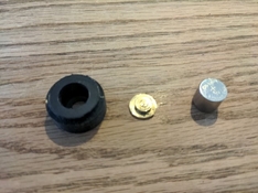
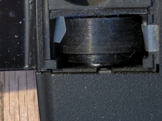
The potentometer built into the aperture dial. The round metal disc on the bottom has a finger (7 o'clock) which contacts a carbon (i guess) resistive strip that wraps around the inside of the dial (can't see it in the photo, it's black). The funny shaped metal prongy thing is the other contact (the wiper). The wiper has a small bundle of whiplike contacts starting at 3 o'clock which contact the resistive strip around 11 o'clock. When installed, the dial rotates, but the wiper is stationary. It appears to me that the meter is intended to be calibrated by rotating the fixed position of the wiper slightly using the two prongs (currently pointing at 3.5).

This board is normally attached to the inside of the front panel and holds the CdS cell and the aperture dial/potentiometer (dial is removed in this photo). The dial screws into the middle of the metal donut at 9 o'clock (which is a contact that connects the wiper to the large square solder blob). The dogleg shaped contact above the donut makes contact with the disc-like contact at the bottom of the aperture dial.

The other side of that board. This is normally obscured by a plastic bit with a rotating mask over it that is interfaced with the ISO selector on the front of the camera to change how much light hits the CdS sensor (the little can-with-a-window-in-it).
My current theory is that the CdS sensor has gone bad. It does respond to light, but currently the maximum resistance of the sensor (when I block all light from entering the sensor) is about 3kOhm. Minimum resistance (when I shine a fairly bright light at it) is a couple hundred ohm. The variable resistor in the aperture dial goes from about 1.6kOhm to 22kOhm. If my read of the service manual is correct, for the metering circuit to work correctly the CdS cell would need to vary over the same range because it needs to match resistance with the dial at the appropriate aperture.
It appears that the CdS cell typically has ~2kOhm resistance when installed behind the ISO mask (varying by a couple hundred ohm either way depending on light and setting. That corresponds roughly to the resistance of the aperture dial/potentiometer when set somewhere in the vicinity of f/16 -f/22, so I feel reasonably confident I've got the culprit. The couple hundred ohm variance under different lighting conditions would be barely noticeable on the dial (the next stop smaller[numeric] is over 1kOhm more).
I have no idea what sensitivity min/max resistance CdS cell the original circuit design might have called for (nor, if I'm honest, do I really fully understand how CdS photoresistors are even specified). To start with, I ordered a smattering of photoresistors with different values from digikey and plan to install them one at a time and see which ones appear to generate reasonable when I shine a normal amount of light through the sensor opening. Doesn't have to perfectly match whatever the factory sensor would have been, just needs to be close enough that I can calibrate the meter to be good enough (I hope, never done this before, just having fun).
.jpg")
The original sensor is in a hermetically sealed housing that appears to my calipers to be a TO-52 can (5.5mm dia, 3.4mm height). I couldn't find any new CdS cells in a TO-52, and all the other hermetically sealed cells came in bigger packages that wouldn't have fit inside of the housing. Instead I just ordered (cheaper) ceramic/epoxy cells which should fit in the housing (they're about 4.5mm dia).
Will provide more updates as parts come in and I try stuff out!
I have a real sweet spot for this camera - it has a focusing lens, a meter, and a larger-than-usual frame size. Old minolta plastic casettes are relatively easy to find and reload (compared to some of the more exotic casettes for other high quality sub-minis). Generally, it works fine, I've shot a couple rolls of Kodak 250D through it (fun, but I rarely have color chemicals mixed up) and it makes images, but the meter has always been busted. The meter on this is a kind of electronic-match-needle style. The camera has two shutter speeds, 1/30 and 1/250, lens goes f/3.5 - f/22. There's a button next to the aperture dial which you press while rotating the dial, that closes a contact and lights up one or two LEDs in the viewfinder to tell you if you're over/under/right-on. Mine has always reported that some aperture between f/16 and f/22 is right-on regardless of the film or shutter speed. The metering circuit generally is working (lights come on, and turning the dial all the way to 22 reports under-exposure, and less than 16 reports over), but it's apparently totally non-responsive to actual light changes.
This camera is pretty cheap and ordinarily I might just grab another and hope for the best, but a) seems like a fun project and b) I found some evidence that this is possibly a common problem on these cameras (so I might be in the same boat with another unit).
The service manual has an EXCELLENT very detailed explanation of the meter circuit - it uses a differential amplifier which is basically a voltage comparator implemented with a pair of darlington transistors.
A voltage divider is created by a potentiometer built into the aperture dial and the CdS photocell. When the resistance of the CdS cell matches that of the aperture dial, the circuit will alternate blinking the over/under exposure LEDs in the viewfinder to indicate correct exposure.
The potentometer built into the aperture dial. The round metal disc on the bottom has a finger (7 o'clock) which contacts a carbon (i guess) resistive strip that wraps around the inside of the dial (can't see it in the photo, it's black). The funny shaped metal prongy thing is the other contact (the wiper). The wiper has a small bundle of whiplike contacts starting at 3 o'clock which contact the resistive strip around 11 o'clock. When installed, the dial rotates, but the wiper is stationary. It appears to me that the meter is intended to be calibrated by rotating the fixed position of the wiper slightly using the two prongs (currently pointing at 3.5).
This board is normally attached to the inside of the front panel and holds the CdS cell and the aperture dial/potentiometer (dial is removed in this photo). The dial screws into the middle of the metal donut at 9 o'clock (which is a contact that connects the wiper to the large square solder blob). The dogleg shaped contact above the donut makes contact with the disc-like contact at the bottom of the aperture dial.
The other side of that board. This is normally obscured by a plastic bit with a rotating mask over it that is interfaced with the ISO selector on the front of the camera to change how much light hits the CdS sensor (the little can-with-a-window-in-it).
My current theory is that the CdS sensor has gone bad. It does respond to light, but currently the maximum resistance of the sensor (when I block all light from entering the sensor) is about 3kOhm. Minimum resistance (when I shine a fairly bright light at it) is a couple hundred ohm. The variable resistor in the aperture dial goes from about 1.6kOhm to 22kOhm. If my read of the service manual is correct, for the metering circuit to work correctly the CdS cell would need to vary over the same range because it needs to match resistance with the dial at the appropriate aperture.
It appears that the CdS cell typically has ~2kOhm resistance when installed behind the ISO mask (varying by a couple hundred ohm either way depending on light and setting. That corresponds roughly to the resistance of the aperture dial/potentiometer when set somewhere in the vicinity of f/16 -f/22, so I feel reasonably confident I've got the culprit. The couple hundred ohm variance under different lighting conditions would be barely noticeable on the dial (the next stop smaller[numeric] is over 1kOhm more).
I have no idea what sensitivity min/max resistance CdS cell the original circuit design might have called for (nor, if I'm honest, do I really fully understand how CdS photoresistors are even specified). To start with, I ordered a smattering of photoresistors with different values from digikey and plan to install them one at a time and see which ones appear to generate reasonable when I shine a normal amount of light through the sensor opening. Doesn't have to perfectly match whatever the factory sensor would have been, just needs to be close enough that I can calibrate the meter to be good enough (I hope, never done this before, just having fun).
The original sensor is in a hermetically sealed housing that appears to my calipers to be a TO-52 can (5.5mm dia, 3.4mm height). I couldn't find any new CdS cells in a TO-52, and all the other hermetically sealed cells came in bigger packages that wouldn't have fit inside of the housing. Instead I just ordered (cheaper) ceramic/epoxy cells which should fit in the housing (they're about 4.5mm dia).
Will provide more updates as parts come in and I try stuff out!
Last edited: