Metz 76 mz-5 no charging noise and no flash

Mark's Workshop

H
Mark's Workshop

  • 0
  • 1
  • 42
Yosemite Valley.jpg

H
Yosemite Valley.jpg

  • 2
  • 0
  • 53
Three pillars.

D
Three pillars.

  • 1
  • 2
  • 58
Water from the Mountain

A
Water from the Mountain

  • 4
  • 0
  • 88
Rijksmuseum Amsterdam

A
Rijksmuseum Amsterdam

  • 0
  • 0
  • 77

Recent Classifieds

Forum statistics

Threads
197,525
Messages
2,760,631
Members
99,396
Latest member
Emwags
Recent bookmarks
0

sadmetz76

Member
Joined
Dec 27, 2022
Messages
15
Location
europe
Format
Digital
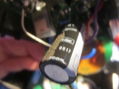
My older 76mz-5 refuses to flash anymore .

No smell , No charging-noise ( the typical charging sound ) , No flash , No bang ,
control unit is working , albeit without the red and green indicator
NO flash-ready indicator .

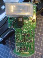
capacitor failure ? after all those years highly possible .

can it be something else ?

batteries are tested and all above 2000 mah and nicely at 10+ volt .

How to get this flash apart ?
Any ideas on what might be wrong

anyone schematics ?

all help highly appreciated .
 
OP
OP

sadmetz76

Member
Joined
Dec 27, 2022
Messages
15
Location
europe
Format
Digital
i managed to open the unit without damaging it ,
turns out the capacitor is in the head .

now to find out the way to get it out .

i have made numerous pictures , so if someone is interested download the zip .
 

Attachments

  • metz 76mz-5 disassembly pt 1.ZIP
    1.8 MB · Views: 109
  • metz 76mz-5 disassembly pt 2.ZIP
    504.6 KB · Views: 106
OP
OP

sadmetz76

Member
Joined
Dec 27, 2022
Messages
15
Location
europe
Format
Digital
m_IMG_3721.jpg

Now , how to get to the capacitor ( which has NO load ) without damaging the plastic structure
Is there another hidden screw ??


again any help highly appreciated .

does anyone have the schematic ?
 

koraks

Moderator
Moderator
Joined
Nov 29, 2018
Messages
20,872
Location
Europe
Format
Multi Format
What's the capacity and rating of the electrolytic in this image?


turns out the capacitor is in the head .

If that's the case, you could do some elementary measurements on it without removing it. Just desolder one of its leads and perform a capacity measurement on it with an appropriate meter. I use a generic but relatively modern Chinese DMM for this.

However, in my experience with circuits like these, other parts are at least as likely to die. Especially the charging transistor, which I assume is probably a MOSFET given the relative modern electronics. If I were to hazard a guess, the TO-220 component sticking out of the PCB next to the long electrolytic I asked about before is probably the switching transistor that switches the primary side of the transformer. I'd pry off the insulation off of that one, see what type it is and do some measurements on it; especially check for a short between source and drain if it's a MOSFET. Also measure the resistance of the large, rectangular yellow PTC which likely protects the primary circuit from excess currents. These PTC's sometimes die with no apparent cause or side-effects.
 
OP
OP

sadmetz76

Member
Joined
Dec 27, 2022
Messages
15
Location
europe
Format
Digital
Koraks ,

the sticking up component is a ;

G4BC40W-L bipolar transistor specific for switch mode power applications

the similar component on the other side of the capacitor is a ;

8G103 bipolar transistor specific for flash applications

The ptc is an ;

RGEF800 resettable fuse

- no resistance measurable
 
OP
OP

sadmetz76

Member
Joined
Dec 27, 2022
Messages
15
Location
europe
Format
Digital
long capacitor next to bipolar transistor ;

metz 331 48 0017

measures around 145 uF
 

koraks

Moderator
Moderator
Joined
Nov 29, 2018
Messages
20,872
Location
Europe
Format
Multi Format
measures around 145 uF

Sounds plausible; what does the text on the capacitor say? You might have to bend it upwards to read the text that's on the PCB side. Caps like these will always have uF and voltage ratings printed onto them as well as a polarity mark.
Btw, upon consulting the user manual for this unit I suspect this particular cap is probably for the auxiliary reflector/flash tube that's in the handle underneath the swiveling head. It's evidently too small for the main flash cap.

G4BC40W-L bipolar transistor specific for switch mode power applications

the similar component on the other side of the capacitor is a ;

8G103 bipolar transistor specific for flash applications
Ok; thanks
For the G4BC40W there's a datasheet here: https://datasheetz.com/data/Discrete Semiconductor Products/IGBTs - Single/IRG4BC40W-datasheetz.html
8G103: https://pdf1.alldatasheet.com/datasheet-pdf/view/214271/TOSHIBA/GT8G103.html

Gate-emitter should measure more or less like a normal diode on both of these, so 0.7V or thereabouts. Emitter-collector should measure very high or infinite resistance: https://www.allaboutcircuits.com/textbook/semiconductors/chpt-4/meter-check-transistor-bjt/

Do you have access to an oscilloscope?

PS: what does the main cap measure?
Please note you should disconnect a cap (at least one of the leads) for a reliable in-circuit measurement.
 
OP
OP

sadmetz76

Member
Joined
Dec 27, 2022
Messages
15
Location
europe
Format
Digital
i would like to get access to the main cap .

that part of the disassembly is rather unclear and it interlocks in a rather specific way ( unfortunately ) .

if i could open its compartment it would be possible to measure .

helaas niet open te krijgen
 

Attachments

  • m_IMG_3729.jpg
    m_IMG_3729.jpg
    85.9 KB · Views: 84
  • m_IMG_3730.jpg
    m_IMG_3730.jpg
    450.8 KB · Views: 95

koraks

Moderator
Moderator
Joined
Nov 29, 2018
Messages
20,872
Location
Europe
Format
Multi Format
helaas niet open te krijgen

Yeah, that's annoying. I don't have one of these at hand either so I can't help with that bit. I usually try to pry along the different seams of the components and see where they start to separate, and then figure out from there how it's supposed to go apart.

But I think you should be able to measure the main cap without prying open that compartment provided that the red and brown leads are the ones to go to the main cap. The polarity one should be able to deduce from the PCB connection; it's either marked explicitly or it can be deduced from the circuit. Do you have a photo of where red & brown go into the PCB?
 

koraks

Moderator
Moderator
Joined
Nov 29, 2018
Messages
20,872
Location
Europe
Format
Multi Format
Well, find brown and then work out based on the circuit which one is the positive terminal of the cap and which one the negative.
Or alternatively just measure in both directions and see which gives the most plausible outcome.
 
OP
OP

sadmetz76

Member
Joined
Dec 27, 2022
Messages
15
Location
europe
Format
Digital
i don't like working without schematics , but with your help we slowly go forward :smile:

if only i could get the capacitor-holder to open ..............
 

koraks

Moderator
Moderator
Joined
Nov 29, 2018
Messages
20,872
Location
Europe
Format
Multi Format
i don't like working without schematics

Me neither!! Too bad it's uncommon to have one at hand for stuff like this.

Btw, it shouldn't be too difficult to draft a schematic for (most of) the charging circuit. It seems to be localized mostly on that single PCB, which appears to be only doublesided (no hidden layers) with relatively few components. I'd be tempted if I had it in my hand...

if only i could get the capacitor-holder to open ..............

I know, but honestly, what do you hope to find there? There'll be a cap, roughly 1000uF to 2000uF and 360V, and most likely it shows no clear defect from the outside. In fact, it's quite likely it's in decent condition overall.
Sometimes you get stuck on trying to figure something out that in hindsight only turns out to be a distraction.

Do you have a scope to observe the charging behavior? Have you done some simple measurements with a DMM to see if you can find anything sensible?
 
OP
OP

sadmetz76

Member
Joined
Dec 27, 2022
Messages
15
Location
europe
Format
Digital
no measurements yet as i only was able to open it today.

scope is at hand , dmm , lc-tester too .

there is no charging sound at all ( the typical whining ) , and no flash-ready light .
the rest of the flash seems to be working ( zoom and the camera adapter/keyboard )
there is no green and red led on the keyboard , as is obvious becouse of the lack of the ready light on the flash itself.

i had the same problem with my trusted 45ct4 sca when the cap was dead .

time for a thee
 

koraks

Moderator
Moderator
Joined
Nov 29, 2018
Messages
20,872
Location
Europe
Format
Multi Format
i had the same problem with my trusted 45ct4 sca when the cap was dead .

I can see the desire to get to that cap then.

I'd suggest ensuring the main cap is discharged, hook up a scope to the base of that G4BC40W, then turn on the flash and see if attempts to modulate the primary coil of that transformer. If there's a block pattern there, do some measurements on the transistor itself; particularly check if it's energizing the primary coil. You won't get that far likely as you'd otherwise hear the whining noise alright.

In a parallel track I'd inspect that charging PCB to figure out what kind of active safety they use to control the charging process. Some insight into that would help to verify it's a dead cap or a different malfunction.


time for a thee

Time for a movie here; will probably check back tomorrow with you. Good luck, it's a nice puzzle.
 
OP
OP

sadmetz76

Member
Joined
Dec 27, 2022
Messages
15
Location
europe
Format
Digital
the problem now ;

how to get to the capacitor ,
i can open its holder a wee bit , but it certainly is not the correct way to open it as i need to put on much more force that is good for the design .

i think the turning-mechanism of the head has a clever design to take away a part so the locked bit of the cap-holder can be removed .

as my aim is to repair the flash i need to be gentle here .
m_IMG_3740.jpg
m_IMG_3739.jpg
 
OP
OP

sadmetz76

Member
Joined
Dec 27, 2022
Messages
15
Location
europe
Format
Digital
unfortunately the part of the cap i can see does not have any marking on it ................
 
OP
OP

sadmetz76

Member
Joined
Dec 27, 2022
Messages
15
Location
europe
Format
Digital
Hi forum ,

so i finally managed to open the cap holder ,

m_IMG_3775.jpg

m_IMG_3780.jpg

m_IMG_3781.jpg

m_IMG_3782.jpg

so , as i can only see the cap looks okay at 3300 uf , it was 0 Volts .

what will repair this flash ??


any help highly appreciated .

osc. at hand
 

koraks

Moderator
Moderator
Joined
Nov 29, 2018
Messages
20,872
Location
Europe
Format
Multi Format
Yes, looks OK, but there's a slight chance it doesn't perform the same under high voltage. However, given the measurement you've got, I wouldn't prioritize a goose chase in this direction at this point.

Have you scoped the charging behavior? And performed some measurements on the switching FET at the primary side of that HF charge transformer?
 
OP
OP

sadmetz76

Member
Joined
Dec 27, 2022
Messages
15
Location
europe
Format
Digital
@ koraks ,
no time for futher testing yet .

i need an empty workdesk to do that , and right now other repairs do cover up my space .

will post if i found time to do some testing
 
OP
OP

sadmetz76

Member
Joined
Dec 27, 2022
Messages
15
Location
europe
Format
Digital
too much things to do ,
luckily i got a quite nice sony F56 flash to help me out during the repair of the 76 .

unfortunately , metz 45 are not of any help ( got several of those oldies )
 
Photrio.com contains affiliate links to products. We may receive a commission for purchases made through these links.
To read our full affiliate disclosure statement please click Here.

PHOTRIO PARTNERS EQUALLY FUNDING OUR COMMUNITY:


Ilford ADOX Freestyle Photographic Stearman Press Weldon Color Lab Blue Moon Camera & Machine
Top Bottom