Measuring off-axis resolution

Rouse st

A
Rouse st

  • 3
  • 3
  • 37
Do-Over Decor

A
Do-Over Decor

  • 1
  • 1
  • 81
Oak

A
Oak

  • 1
  • 0
  • 68
High st

A
High st

  • 10
  • 0
  • 96

Recent Classifieds

Forum statistics

Threads
199,231
Messages
2,788,227
Members
99,836
Latest member
Candler_Park
Recent bookmarks
0
OP
OP
BetterSense

BetterSense

Member
Joined
Aug 16, 2008
Messages
3,151
Location
North Caroli
Format
35mm
Yes, print several USAF1951 resolution charts and pin them to a wall so one ends up in the center of your image and another in the corner.

This is not a flawed suggestion, it just utterly fails to address my question.

My question: "explicitly to avoid doing (obvious thing A), will (possibly equivalent thing B) work?"

Everyone:"why don't you do (obvious thing A)?"

I am doing experiments on an optical bench. Because of the size of my detector and nature of my monochromatic light source, I have only a small angle to work with. I have to test off-off - axis resolution by moving my small detector to the edge of the "film gate", or equivalently, tilting the lens to accomplish the same thing. At that point, if I wanted to fully emulate a camera, I would tilt the detector at the same angle of the lens, causing inverse square falloff, and then to fix the fact that the resolution chart now appears distorted on the detector, I also have to tilt the resolution chart by the same angle. I currently do not see the point of doing either of these 2 last things since the only thing I seem to "gain" is uneven lighting across the detector, plus the fact that the left and right sides of the resolution chart are now different distances.
 

Xmas

Member
Joined
Sep 4, 2006
Messages
6,398
Location
UK
Format
35mm RF
This is not a flawed suggestion, it just utterly fails to address my question.

My question: "explicitly to avoid doing (obvious thing A), will (possibly equivalent thing B) work?"

Everyone:"why don't you do (obvious thing A)?"

I am doing experiments on an optical bench. Because of the size of my detector and nature of my monochromatic light source, I have only a small angle to work with. I have to test off-off - axis resolution by moving my small detector to the edge of the "film gate", or equivalently, tilting the lens to accomplish the same thing. At that point, if I wanted to fully emulate a camera, I would tilt the detector at the same angle of the lens, causing inverse square falloff, and then to fix the fact that the resolution chart now appears distorted on the detector, I also have to tilt the resolution chart by the same angle. I currently do not see the point of doing either of these 2 last things since the only thing I seem to "gain" is uneven lighting across the detector, plus the fact that the left and right sides of the resolution chart are now different distances.

B wont be meaningful necessarily it is lowest risk to do the full reference test of wasting two sheet films in your camera and using a microscope on the negatives.

The MTF test that a lens designer looks at is merely a go no test before handing the prototype to a test photog the designer knows what the MTF should be from his design optimisation software... If it does not meet the predicted MTF he may go back to the prototype shop with a query instead... The MTF is not the only test the designer will use as a release criteria.

The production test people may test samples for MTF as well...

If you know what the results should be you would not be posting.
 

Jim Jones

Subscriber
Joined
Jan 16, 2006
Messages
3,740
Location
Chillicothe MO
Format
Multi Format
If you slide the detector and chart in opposite directions while keeping them in parallel planes, you will not distort the chart in the detector. The left and right sides of the resolution chart will indeed be at slightly different distances, which is perfectly normal in real life. If any uneven lighting across the detector is a problem, it can be corrected by uneven lighting of the chart. That will probably be unnecessary in any but the most critical tests, certainly not in testing pinhole diffraction.
 

Jim Jones

Subscriber
Joined
Jan 16, 2006
Messages
3,740
Location
Chillicothe MO
Format
Multi Format
. . . do you have a source for the graphs you posted? Fascinating.

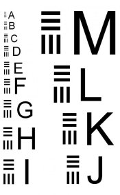
I did the tests and graph posted above for a college project in pinhole photography in 1979. The film was panchromatic, the lighting was probably about 2800K incandescent. The improvised camera was donated to Pinhole Resource decades ago. The chart was hand-drawn, somewhat similar to the one below, and photo-reduced as necessary. As I recall, that chart omitted the letters to make it more compact. It is interesting to note that an optimum size pinhole can resolve line pairs with a spacing smaller than the pinhole diameter, contrary to what a few "experts" have claimed, apparently without doing the experiments.
 

Attachments

  • RES-abc.jpg
    RES-abc.jpg
    32.9 KB · Views: 70
Last edited by a moderator:
Photrio.com contains affiliate links to products. We may receive a commission for purchases made through these links.
To read our full affiliate disclosure statement please click Here.

PHOTRIO PARTNERS EQUALLY FUNDING OUR COMMUNITY:


Ilford ADOX Freestyle Photographic Stearman Press Weldon Color Lab Blue Moon Camera & Machine
Top Bottom