LED UV printer heat management

Kuba Shadow

A
Kuba Shadow

  • 1
  • 0
  • 18
Watering time

A
Watering time

  • 2
  • 0
  • 44
Cyan

D
Cyan

  • 3
  • 0
  • 36
Sunset & Wine

D
Sunset & Wine

  • 5
  • 0
  • 38

Forum statistics

Threads
199,104
Messages
2,786,209
Members
99,813
Latest member
Left 2
Recent bookmarks
3

Fraunhofer

Member
Joined
Jan 1, 2016
Messages
208
Location
East coast
Format
Multi Format
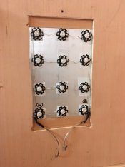
So, I've built a 4x5 exposure unit using 12 UV LEDs, 3W each, 395nm like so
2.JPG

which works fine and I get exposure times of a few minutes (~3) for ziatypes with very even illumination. So far so good.

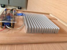
I am using a fairly massive heat sink
1.JPG

but still the heat sink goes to about 58C after 5 minutes or so and you don't want to run the LED's much above 65C.

I am wondering how to do this for a large unit, say 11x14?

The sheer weight of the aluminum in the heat sink becomes a real concern (as well as the cost). I've seen reports of LEDs which were just glued to a sheet of thin aluminum and the light output dropped to less than 1/2 after a year of printing, which to me sounds like to much heat at the junction.

So how to manage heat if you have of the order of 200W of LED's?
 

tim_walls

Member
Joined
Sep 6, 2006
Messages
1,122
Location
Bucuresti, R
Format
35mm
Looks very nice :smile:.

Without wishing to state the obvious... A fan?? For simplicity's sake, a* heatsink with built in fan designed for something like a computer video card would be more than capable, and an array of those would almost certainly be lighter than a single massive heatsink.

I've not really done that maths, but as your area of lights increases also, you may even find passive cooling still works just fine. Assuming you cover the entire surface, your surface area of heatsink (taking into account the fins) will increase faster than the area & power of the lights, so you may even find it easier to passively cool the larger array and might be able to use a lighter heatsink, or a single large heatsink and heatpipes to cover the whole array (but the latter may be beyond amateur construction.)

Someone who didn't forget all their physics is probably better placed to comment.


Assume you're also using some kind of thermal transfer paste to ensure the 'sink is effective.


* possible more :smile:.
 

nmp

Member
Joined
Jan 20, 2005
Messages
2,029
Location
Maryland USA
Format
35mm
(Disclaimer: I am not among those who didn't forget all their physics.)

If your heat sink is at 58 C, the junction temperature is probably much higher - I am surprised that happens after such a short time of use. It probably also means that the sink is effective. The myth of LED's being cooler is just that - a myth. LED's generate about 15% in light energy, the rest in the form of heat, all of which has to be removed from the back of the chip. An incandescent bulb, on the other hand produces about 5% in light, vast majority of the rest is in the form of IR so it heats everything around it. The heat generation is relatively small portion at 10-15% which goes to the fixture. CFLs are somewhere between the two. I have an unit that I built with a bunch of CFL BLB's and I have measured the temperature on my printing frame, after 40 minutes of exposure, at 80 C!

If you are going to use the same lamp density when you scale up, the heat transfer rate should remain the same (assuming nearly all of the heat is coming out from the top of the heat sink.) So I would expect no change in the steady state temperature, unless there is a convective bottle neck around the unit. In which case, a fan would be helpful. Try using a small fan directed right at the heat sink and see what it does. If there is a lack of circulation in the area where your unit is, this should help immediately.
 
Last edited:
OP
OP

Fraunhofer

Member
Joined
Jan 1, 2016
Messages
208
Location
East coast
Format
Multi Format
Sorry took a while, got side tracked with reversal processing etc.

Thanks for all your replies, and I surely am not supposed to have forgotten physics like this...

In any case, what I was really after was: hey, there is a simple way people deal with this and I am satisfied there isn't. Energy conservation does of course suggest that outcome...
 

DonF

Member
Joined
Jul 19, 2016
Messages
285
Location
Saint Charles, Il
Format
Large Format
So, I've built a 4x5 exposure unit using 12 UV LEDs, 3W each, 395nm like so

View attachment 183779

which works fine and I get exposure times of a few minutes (~3) for ziatypes with very even illumination. So far so good.

I am using a fairly massive heat sink

View attachment 183780

but still the heat sink goes to about 58C after 5 minutes or so and you don't want to run the LED's much above 65C.

I am wondering how to do this for a large unit, say 11x14?

The sheer weight of the aluminum in the heat sink becomes a real concern (as well as the cost). I've seen reports of LEDs which were just glued to a sheet of thin aluminum and the light output dropped to less than 1/2 after a year of printing, which to me sounds like to much heat at the junction.

So how to manage heat if you have of the order of 200W of LED's?


Could you comment on how you are driving the LEDs???? What voltage and how are you limiting the current to each LED? Are you using individual current limiting resistors for each LED or running them all in parallel with a single large resistor?

Best,

Don
 

Jerevan

Member
Joined
Nov 19, 2004
Messages
2,258
Location
Germany/Sweden
Format
Large Format
I'd love to hear more details about the construction too. :smile:
 

jim10219

Member
Joined
Jun 15, 2017
Messages
1,632
Location
Oklahoma
Format
4x5 Format
Beyond heat sinks and a fan, you could set up a fluid cooling system. Many gamer computers which are highly overclocked use liquid cooling systems, so you might be able to find a semi-affordable one from a computer parts retailer and adapt it to your setup.

Also, you could try limiting the current/voltage going to the LED's. As you up the power, you'll up the heat. You'd most likely have to run some tests and plot some curves to know where the sweet spot is that allows for maximum efficiency, or at least a reasonable exposure time without generating too much heat.
 
OP
OP

Fraunhofer

Member
Joined
Jan 1, 2016
Messages
208
Location
East coast
Format
Multi Format
Could you comment on how you are driving the LEDs???? What voltage and how are you limiting the current to each LED? Are you using individual current limiting resistors for each LED or running them all in parallel with a single large resistor?

Best,

Don

Hi Don,

First I used a very cheap 12V constant voltage power supply ($7 on ebay), but I fried that one. So I got a new one, https://www.amazon.com/ABI-Supply-Outdoor-Rainproof-Weatherproof/dp/B01IU8QAUC, which is a single rail 12V power supply and is holding up fine. Note, this supply is with 500W overkill, I bought this size in anticipation of an upgrade to a 11x14 system.

I have three LEDs in series and 4 of these groups of 3 in parallel, so the voltage drop across each LED is ~4V and they are rated for 3.5-4V. In practice the supply voltage drops to about 11.6V under load, so the actual voltage drop is 3.9V.
 
Joined
Nov 5, 2017
Messages
63
Location
Central Scotland
Format
35mm
Be aware that it's generally not advisable to drive power LEDs (or any LEDs actually) in parallel without individual current limiting. Due to manufacturing differences, it is likely that they will share the current unequally, which will cause one to heat more than the other, which worsens the problem due to having a positive temperature coefficient. I.e. there's a positive feedback effect, so it's possible to have thermal runaway.

This is why in mains-powered LED lighting fixtures you'll usually find that all of the LEDs are in series driven by a single current source (though with a fairly high compliance voltage).


As for cooling: it is critically important that you get good thermal contact between the LEDs and the heatsink. Use a proper thermal paste and screws to keep strong clamping pressure on the LEDs, or alternatively, a thermally conductive adhesive (i.e. one designed for this purpose). If you have a datasheet for that heatsink, it should tell you the thermal resistance (in degrees C per watt) which you can use to calculate the expected temperature rise. I'd probably just get a cheap computer fan and strap it on top of the heatsink. Be sure to have the fan blow air into the fins of the heatsink, not suck air past them. The turbulent flow created by blowing onto the fins results in improved heat transfer.
 

jim10219

Member
Joined
Jun 15, 2017
Messages
1,632
Location
Oklahoma
Format
4x5 Format
Be aware that it's generally not advisable to drive power LEDs (or any LEDs actually) in parallel without individual current limiting. Due to manufacturing differences, it is likely that they will share the current unequally, which will cause one to heat more than the other, which worsens the problem due to having a positive temperature coefficient. I.e. there's a positive feedback effect, so it's possible to have thermal runaway.

This is why in mains-powered LED lighting fixtures you'll usually find that all of the LEDs are in series driven by a single current source (though with a fairly high compliance voltage).


As for cooling: it is critically important that you get good thermal contact between the LEDs and the heatsink. Use a proper thermal paste and screws to keep strong clamping pressure on the LEDs, or alternatively, a thermally conductive adhesive (i.e. one designed for this purpose). If you have a datasheet for that heatsink, it should tell you the thermal resistance (in degrees C per watt) which you can use to calculate the expected temperature rise. I'd probably just get a cheap computer fan and strap it on top of the heatsink. Be sure to have the fan blow air into the fins of the heatsink, not suck air past them. The turbulent flow created by blowing onto the fins results in improved heat transfer.
You are correct in most regards. But if any component has a positive heat coefficient, then it should increase resistance and be somewhat self limiting against thermal runway. The effect of temperature has a positive effect on resistance, so the feedback effect on voltage is negative. So LED’s shouldn’t experience thermal runaway. However, it’s still good advice to current limit them, as the individual resistance of each LED will vary, and you can greatly shorten their lifespan if they are operated outside of their specifications, leaving you with eventual dead spots.
 
Joined
Nov 5, 2017
Messages
63
Location
Central Scotland
Format
35mm
Sorry, I misspoke - should have said negative.

From experience, LEDs definitely can experience thermal runaway when wired in parallel. The forward voltage of LEDs (and most other diodes) decreases as temperature increases. Generally this will lead to increased LED current, and hence further heating.

Anyway, for power LEDs in particular it's strongly preferable to use a constant-current source rather than a constant-voltage source. And you only need one current source if you wire them in series - though of course the compliance voltage needs to be at least as high as the sum of the LED forward voltages.
 
Joined
Nov 5, 2017
Messages
63
Location
Central Scotland
Format
35mm
To clarify, you're correct that in general as temperature increases, resistance increases. But it is not the resistance (in wiring etc) which causes the problem.

It makes little sense to talk about the resistance of an LED as LEDs are nonlinear devices - they do not follow ohm's law.
 
OP
OP

Fraunhofer

Member
Joined
Jan 1, 2016
Messages
208
Location
East coast
Format
Multi Format
Duly noted. I have, in the mean time added a current limiter, since my power source is 12V I have to run them in parallel to some degree...

And yes to thermal adhesive.

Overall, LEDs are not much easier than fluorescent tubes, I am afraid.
 

jim10219

Member
Joined
Jun 15, 2017
Messages
1,632
Location
Oklahoma
Format
4x5 Format
Another approach would be to buy a batch of LED’s and measure the forward voltage drop of each. Then sort them according to their measurements to create several series strings of LED’s with a similar voltage drop. You could run several strings of these series LED’s in parallel with one another and use a constant voltage source. Then measure and fine tune them with current limiting resistors for each series LED strings ran in parallel. It wouldn’t be 100% fault proof, but by using a constant voltage source, thermal runaway wouldn’t be an issue. That should contain any damage to just the single component that faulted. You could further regulate each series string with matching FET’s and perhaps opamps to power them (so your LED’s aren’t starved), but then it’s getting more complicated and expensive. That might be a better design for commercial use, but for your purposes, I think the best bet is to keep it simple, cheap, and repairable (i.e. easy to troubleshoot). If you match them well and do some testing to see how the circuit responds to heat and make any necessary corrections, it should be a pretty stable and reliable device. It wouldn’t be practice on a mass production scale, but for a one off, DIY project, I think it makes more sense. At least that’s how I would approach this. I might be overlooking something, but that’s what breadboards are for!
 
Joined
Nov 5, 2017
Messages
63
Location
Central Scotland
Format
35mm
I think by the point that you go that far you are as well using the extremely cheap constant current source modules off ebay for each series string. Less hassle than binning LEDs by forward voltage etc
 

jim10219

Member
Joined
Jun 15, 2017
Messages
1,632
Location
Oklahoma
Format
4x5 Format
That might work too. But voltage regulators are cheap as well, so I don’t know that that would save you any money. They will generate some heat, but you could keep them separate from the LED’s in a separated power supply. And you could breadboard a testing station and sort the LED’s pretty quickly. Plus, that’s the type of stuff I have on hand anyway.

That’s just how I’d do it. There’s more than one way to get to point B.
 
Photrio.com contains affiliate links to products. We may receive a commission for purchases made through these links.
To read our full affiliate disclosure statement please click Here.

PHOTRIO PARTNERS EQUALLY FUNDING OUR COMMUNITY:


Ilford ADOX Freestyle Photographic Stearman Press Weldon Color Lab Blue Moon Camera & Machine
Top Bottom