LED Enlarger Head

first-church.jpg

D
first-church.jpg

  • 1
  • 0
  • 0
Grape Vines

A
Grape Vines

  • sly
  • May 31, 2025
  • 1
  • 0
  • 12
Plot Foiled

H
Plot Foiled

  • 1
  • 0
  • 27
FedEx Bread

H
FedEx Bread

  • 1
  • 0
  • 30
Unusual House Design

D
Unusual House Design

  • 4
  • 2
  • 68

Forum statistics

Threads
197,969
Messages
2,767,405
Members
99,516
Latest member
Fuji_Bro
Recent bookmarks
1

kenh

Member
Joined
Jun 5, 2003
Messages
22
Format
Medium Format
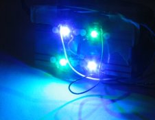
I tried some brief experiments with some green and blue LED's desgined for instrment displays. The one thing that really surprised me is that the VC paper was nearly unresponsive to the green LED. Even making a tiny print, though a very thin negative took a very long time. In fact the paper was so insensitive to the green LED's it made me wonder if they would make a good safe light (I currently use red LED's for a safe light).

I notied that the color of the big bright 1W and 5W green LED that Huws used was different than the ones I was experimenting with (peak emission frequency was different). I suspect that this makes all the difference in the world.

The blue LED's required very short exposures .. but only got me to about grade 4.

Ken
 

rjr

Member
Joined
Aug 30, 2004
Messages
406
Location
Mosel, SW Ge
Format
Medium Format
Jon,

"I'll happily share the schematic if anyone wants to experiment with the LEDs. If you can solder, you can build this pretty easily."

Yes, please! Me being an electronic dummy, but having a friend who already built a few LED darkroom lamps for me... perhaps I can pursue him to solder a head for my Durst Duomat in exchange for your schematics. ;-)
 

Fotohuis

Member
Joined
Sep 6, 2004
Messages
810
Location
Netherlands
Format
Medium Format
On the Photokina 2004 in Köln I saw the prototype of Heiland's split grade cold light unit, build over with high intensity LED's. Green, blue and red. Green and blue for the split grade exposures, red for an overall view of the negative, I think. It was a new development, planned for 2005.
 

Jon King

Member
Joined
Sep 20, 2002
Messages
361
Location
New Hampshir
Format
Medium Format
rjr said:
Jon,

"I'll happily share the schematic if anyone wants to experiment with the LEDs. If you can solder, you can build this pretty easily."

Yes, please! Me being an electronic dummy, but having a friend who already built a few LED darkroom lamps for me... perhaps I can pursue him to solder a head for my Durst Duomat in exchange for your schematics. ;-)

Sorry for the delay, but the holidays have gotten in the way :wink:

I attached a jpg of the schematic as well as a snapshot of my initial light source. This can be easily adapted to digital control if desired. I'm going to use this one to build the mixing box, then adjust the number and power of LED's to get the light output where it needs to be for reasonable printing times, and a more power efficient source - all work to do...


A quick note or two. for M1 I used an IRLIZ14G, but any MOSFET with the proper voltage and current rating should work. Your friend should not have much problem finding something suitable. It will get hot - a good heat sink is necessary. The LEDs also need one. Their light output drops as their temperture increases, so for consistant light output during a printing session, a heat sink is needed here too.

Hope this helps,
 

Attachments

  • lumiled_source_small.jpg
    lumiled_source_small.jpg
    19 KB · Views: 358
  • LED Enlarger Lit.jpg
    LED Enlarger Lit.jpg
    90 KB · Views: 301

Jim Moore

Member
Joined
Oct 24, 2003
Messages
952
Location
Iowa
Format
Large Format
Just wondering how those of you who are building an LED light head are coming along with your projects...

I'm thinking of doing one of these for my 8x10.

Jim
 

Donald Qualls

Subscriber
Joined
Jan 19, 2005
Messages
12,169
Location
North Carolina
Format
Multi Format
Hmmm.

I think there may still be too many engineers involved, here.

What, if I might be so bold as to ask, is wrong with independent timers for the blue and green LED circuits, as opposed to megahertz frequency pulse width modulation to emulate a dimmer? You want Grade 4, you look up Grade 4 on the chart (calibrated according to paper curves and LED output, or by printing actual tests), dial up 30 seconds green, 5 seconds blue (to pick numbers out of the air) and hit "start" (and this could be done with two of the small enlarging timers wired to a single start switch, just to keep things really simple and completely analog -- you're only switching a couple hundred milliamps, after all). When all the lights go out, put the paper in the developer.

As for Huw not getting a full Grade 5 -- I'd guess this is because the color of the blue LED isn't quite right. If the blue overlaps the sensitivity range of the low-contrast, green sensitive component of the paper emulsion, you'll get some response from the lower contrast even at 100% blue. The solution here is probably to get LEDs with shorter wavelength light, such as the "royal blue" mentioned above, or else to filter the blue LEDs through a full cutoff magenta printing filter to eliminate the "yellow" portion of their spectrum. No LED is a true "line" emission like a gas discharge; they have a continuum spectrum, which can be very narrow at low levels of emission, but tends to broaden at higher power outputs (I'm told). If the blue LED emits too much longer wavelength, "greener" light, it would benefit from such filtration for the hardest grade...
 

glbeas

Member
Joined
Sep 25, 2002
Messages
3,913
Location
Marietta, Ga. USA
Format
Multi Format
That would make it work like the Minolta Beseler 45A head in it's additive timer functions. I would admit that your setup would be easier to use than the 45A, it's a royal pain trying to figure where it's going. But when you do get the hang of it, it works very well. I suspect using timers set on seconds and minutes would be a lot more intuitive than the 0-255 setup the 45A used, as well as less limited for longer print times.
 

gainer

Subscriber
Joined
Sep 20, 2002
Messages
3,699
The effective brightness of a pulse modulated led should vary pretty much linearly with the duty cycle, the ratio of on time to total time between on's. The flashing can cause visual problems as it reaches some critical rate that varies with age. I'll have to look that up. I think the flicker frequency increases with age. If you start to get migraines when you see flicker, make the pulse frequency higher.

I think some printing materials do not integrate perfectly with short on periods. These are not unsurmountable problems, as they have apparently been solved for some systems. I think the repetition rate should be rapid enough not to cause visual problems and slow enough not to cause reciprocity (excuse the dirty word) problems. You can vary the effective output enough at some constant pules rate to satisfy most criteria, I think.

Of course, visual problems can be dodged by having continious light for focusing.
 

gainer

Subscriber
Joined
Sep 20, 2002
Messages
3,699
I forgot the possibility of having blue on when green is off. You may not see flicker then, I don't know, but a single knob would set blue-green ratio. Did someone already mention this? My flicker frequency is quite high, so maybe I'm too old.
 

Jon King

Member
Joined
Sep 20, 2002
Messages
361
Location
New Hampshir
Format
Medium Format
JMoore said:
Just wondering how those of you who are building an LED light head are coming along with your projects...

At this moment, my 'darkroom', aka garage, is at a toasty 21F, a good 20-25 degrees higher than it has been for a few weeks. Needless to say, I'm not done. A darkroom with heat and a sink is in the works :wink:

I've built a mixing box that works well for 6x7 , and a full size one for the Durst 138 (5x7). According to an Ilford EM10, illumination is within .2EV for a 4x5 with more falloff on the edges for 5x7. I need to improve the mixing box a bit. With temperatures where they are, I'm not testing with negatives and paper yet. I will definately need more light than the LEDs I have now for the 5x7 head, but I have not figured out the necessary increase in lumens yet.
 

poinsett

Member
Joined
Aug 21, 2004
Messages
3
Format
4x5 Format
The suggestion to use varying times for blue and green separately is a worthy consideration particularly for people familiar with split grade printing. However, it would also be nice to dogde and burn at specific grade values where both lamps are on in proportion needed to generate the grade.
 

Kirk Keyes

Member
Joined
Jun 17, 2004
Messages
3,234
Location
Portland, OR
Format
4x5 Format
Patrick wrote, "Of course, visual problems can be dodged by having continious light for focusing."

So how about adding in a few red LED and leaving that on during the entire expsoure time to cut down on the flickering. It should not affect the paper and should help with focussing.
 

Huw

Member
Joined
Oct 24, 2004
Messages
7
Location
Maidenhead U
Format
35mm Pan
Hi all, I am most flattered. Just to clear up a couple of points that might not be clear on my website.

1. The 5x4 head uses royal blue LEDs, as does the 6x6 one now.

2. The PWM is converted into linear current, no flicker.

3. 'Give an engineer a project he throws a processor at it', true but it also communicates with the RH Analyser, saves me forgetting.

4. I have done a unit for someone else (it's on pnet) with PWM, seems to make no difference.

Feel free to mail me if you have any questions.
 

Curt

Member
Joined
Sep 22, 2005
Messages
4,618
Location
Pacific Nort
Format
Multi Format
Hello Huw, not being an EE I got stalled on the schematics and part numbers etc.. I did some research with the LED manufacturers, it's as though they didn't want any LED's put into use with enlarger heads. If I could only figure it out I would still like to make a 5x7 inch size light source. If it could be dummied down, never thought I would use that term, I would enjoy building the unit. Any other people interested in a split grade filtering head using LED's that could be built and adapted to, say a Beseler or other 4x5 enlarger?
 

paul ewins

Member
Joined
Jan 5, 2006
Messages
446
Location
Melbourne, A
Format
4x5 Format
Yes, I'd love something that could be attached to a Beseler 45. Trouble is that I'm not very good with electronics. I could solder robust components in place but very fine soldering would be trouble for me. Once the electronic side is done I would be fine with making it fit the Beseler.
It would be nice to have something that was modular. I want to build an 8x10 enlarger and it would be nice if I could just connect 4 4x5 boards together to make an 8x10 board. Of course that will have to wait until the price of LEDs drops a lot more.
 

Chan Tran

Subscriber
Joined
May 10, 2006
Messages
6,712
Location
Sachse, TX
Format
35mm
Bob I think the fact the the LED emit the same color at varying power is advantagous for color printing. I have to check but I think I can find LED that emit at the wave length where the paper material is most sensitive. I meant for the 3 layers in the emulsion. The only problem is that I don't think color analyzer would work any longer as they are designed to measure a broarder spectrum.
 

Chan Tran

Subscriber
Joined
May 10, 2006
Messages
6,712
Location
Sachse, TX
Format
35mm
Checking at Kodak website for Supra Endura paper and they are most sensitive at 475, 550 and 710. At the super bright LED website you can find 470nm blue LED, 525nm Green LED and 630nm Red LED. I think they are close enough to work well. You can either pulsing the LED rapidly or control their current to selectively exposing the 3 sensitive layers.
 

herb

Member
Joined
Jan 22, 2005
Messages
404
Format
Medium Format
Led's for Enlarging

I had begun a look at enlarging AZO, in hopes of getting past the size limitation of contact printing.

I got as far as contacting Cree Research, that makes Led's and they put me onto one of their customers, who has a "light engine" that uses 11 cree xlamps that produces 2200mw of UV. The lamps are in a six inch circle.

If any body is interested, the vendor is

Anthony Vilgiate,
Infinilux, Inc
1021 Mateo Camino
Woodland Park, CO 80863
email: anthony@infinilux.com
enjoy
 

harri129

Member
Joined
Sep 27, 2006
Messages
11
Format
35mm
I opted for constant current for my led head I'm working on. I'm worried about the response of different papers at high frequency short pulses. If the frequency is not high enough fades could get actually stepped. (Consider eg. 100Hz short pulses and a faded dodge/burn).

I'm probably going to include light level measurement for feedback (led output drops very much as it heats!). The other possibility is is to measure temperature of the heat sink and calculate indirectly the die temperature when the power level is known. The prototype will show the exact method or combination.

Software features and calibration procedures are hard part for me because I'm including a Zonemaster type measurement (with some differences). I've desided not to make controls like "blue full, green 50%" which I'd prefer because that cannot be transfered easily from one paper to another. Working with grades (based on paper calibration!) simplifies working with different papers a lot.

I'm suprised I've seen no RGB heads yet. I'm definately including red channel too for safe light (B&W) and color prints as well. (Oh yes, another "simple" software feature to come later on: color printing!)

No idea yet what type of measurement/control I'll do for color but for B&W I'll measure green and blue output separately. Measuring both green and blue gives me consistence for negatives with a colored stain as well. I'll simplify measuring by pulsating channels and syncronizing measurements.

The electronics is actually pretty simple and the features are mostly in the software. Basically all you need is an adjustable current source for led channels combined with an intelligent timer (plus input from controls and measuring probes). Being an engineer I'll just have to thow in those for everything :smile:

Features like flashing is also easy to do with the fast turn on/off the leds have (assuming a fast current control loop). Another simple software feature to add. Based on some early prototyping I'm going for mixing chamber. Getting even light output without heavy diffusers is a real pain.
 

harri129

Member
Joined
Sep 27, 2006
Messages
11
Format
35mm
I'll consider giving more details on my project if it gets documented well enough to be published. I'm definate my project takes quite a while to get finished though.

Basics for my project are like this: Adjustable current sources for rgb channels, a lot similar to previous schematics on this thread. Couple op amps and detector diodes for measurements. CPU has analog outputs for current sources, analog inputs for measurements. Everything else is done by software.

My basic idea is to keep electronics very simple. Once you have a couple measurement channels (for baseboard and mixing chamber light level), know the heat sink temperature and can control the light level you're done. With those components you can create almost everything with software.

I started with an idea of Heiland Splitgrade type controllable G/B light source including the timer. Unfortunately that can give very diffent pictures for different paper types with different responses. So, I'll include a measured table for each paper to get actual contrast on a paper independent scale. Most measuring systems seem to have reference points at just visible white and just visible black. The difference between these is the ISO R-speed which correlates well with contrast grades. B&W zones are just some steps between these two points.

Paper manufacturers document ISO P-speed as well. However, I'm considering using the white reference point as a speed reference (to avoid adding any extra measurements). That's what one would basically do for split grade printing as well.

The real pain is in the calibration. Software must include methods for easy calibration or the head is not that usable really. My goal is at 1% absolute repeatability which means reasonably accurate measurements and the need to do runtime correction during a long exposure as well. (Heat changes => light level changes)

Basically I'll probably measure a base line to get a correction table depending on power level and temperature. That get's me close and the tiny correction is left for the runtime during exposure.

I'm adding features one by one. I have a complete goal known pretty much so I can design user interface and the input/outputs for accessory harware coming later on. I'll start by using a simple guessed/measured G/B table for contrast and probably a density based RGB as well for color. That allow me to print. Then I'll add more features one at a time over a longer period.

If anyone has good insite or references how to make a very usable color metering system I'm interested on all ideas. I'm not very familiar with color metering systems at this point.
 

Curt

Member
Joined
Sep 22, 2005
Messages
4,618
Location
Pacific Nort
Format
Multi Format
I'll consider giving more details on my project if it gets documented well enough to be published. I'm definate my project takes quite a while to get finished though.

Basics for my project are like this: Adjustable current sources for rgb channels, a lot similar to previous schematics on this thread. Couple op amps and detector diodes for measurements. CPU has analog outputs for current sources, analog inputs for measurements. Everything else is done by software.

My basic idea is to keep electronics very simple. Once you have a couple measurement channels (for baseboard and mixing chamber light level), know the heat sink temperature and can control the light level you're done. With those components you can create almost everything with software.

I started with an idea of Heiland Splitgrade type controllable G/B light source including the timer. Unfortunately that can give very diffent pictures for different paper types with different responses. So, I'll include a measured table for each paper to get actual contrast on a paper independent scale. Most measuring systems seem to have reference points at just visible white and just visible black. The difference between these is the ISO R-speed which correlates well with contrast grades. B&W zones are just some steps between these two points.

Paper manufacturers document ISO P-speed as well. However, I'm considering using the white reference point as a speed reference (to avoid adding any extra measurements). That's what one would basically do for split grade printing as well.

The real pain is in the calibration. Software must include methods for easy calibration or the head is not that usable really. My goal is at 1% absolute repeatability which means reasonably accurate measurements and the need to do runtime correction during a long exposure as well. (Heat changes => light level changes)

Basically I'll probably measure a base line to get a correction table depending on power level and temperature. That get's me close and the tiny correction is left for the runtime during exposure.

I'm adding features one by one. I have a complete goal known pretty much so I can design user interface and the input/outputs for accessory harware coming later on. I'll start by using a simple guessed/measured G/B table for contrast and probably a density based RGB as well for color. That allow me to print. Then I'll add more features one at a time over a longer period.

If anyone has good insite or references how to make a very usable color metering system I'm interested on all ideas. I'm not very familiar with color metering systems at this point.

Sorry, no disrespect, but I don't think you can do it; that said I don't think that if you could do it that you would give for free any information on it. If you did give it for free, it would in all probability be too complicated for anyone else to build.
 

harri129

Member
Joined
Sep 27, 2006
Messages
11
Format
35mm
First a correction. Heiland Splitgrade is calibrated to papers. I incorrectly wrote it is not while I was thinking on another product that is more like a G/B VC-head.

I've been designing this for quite some time. Checking the backgrounds and figuring out how to do these is a nasty job. Lots and lots of designing seems no progress but it will speed things up pretty soon a lot. Having checked the facts has made me feel a lot safer on the success.

I surely undestand all the doubts. This is not the most simple project. Please be free to point out any unrealistic ideas stated so far about my design.

I'd also point out that there are already several such products (or parts of it). Many measurement products and led heads and vc heads are out there. This will be just another. Those have and can be done. The most simple ones I know of measure just zone I and zone ix references and gets measured points (or extremes there).

I'm sure the average Joe will not be able to replicate my "product" even with full documents and full source code/software. There will be a couple real hard circuit parts and noice protection will be essential in some part of the device. Replicating should on the other hand be simple for anyone with some expertice on this field.

I'll give updates on my progress later on. My goal is not on a commercial product (no intrest in marketing nor finding someone with customer support to market it for me). Mechanical design makes it also not good for mass production. Units will need individual calibration as well (very bad for a commercial product but ok for a single one).
 

swdick

Member
Joined
Mar 28, 2011
Messages
12
Format
35mm
Any progress

Harri129, have you made any progress since your last post?
I'm designing a timer and LED head but a lot simpler than yours.
It just mixes Green and Blue to get the filtergrades for B/W printing.

If your interested I can send my sketch for the Arduino. It is not tested yet however.
I would be interested in your software.
 
Photrio.com contains affiliate links to products. We may receive a commission for purchases made through these links.
To read our full affiliate disclosure statement please click Here.

PHOTRIO PARTNERS EQUALLY FUNDING OUR COMMUNITY:


Ilford ADOX Freestyle Photographic Stearman Press Weldon Color Lab Blue Moon Camera & Machine
Top Bottom