• Welcome to Photrio!
    Registration is fast and free. Join today to unlock search, see fewer ads, and access all forum features.
    Click here to sign up

LED Enlarger Head - Update

Recent Classifieds

Forum statistics

Threads
203,292
Messages
2,852,470
Members
101,766
Latest member
Onetrick
Recent bookmarks
0

Steve Smith

Member
Allowing Ads
Joined
May 3, 2006
Messages
9,110
Location
Ryde, Isle o
Format
Medium Format
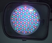
As some of you may be aware, I have recently converted a DeVere 54 enlarger to LED lighting using the tri-colour PCB from an LED stage light.

Last night I finally got round to making some prints and I am very pleased with the results...... which I can't show you yet as I didn't have enough fixer!!! I made up a weak mixture with the little I had but all the prints I made have darkened. I will order some more and make some prints which I can show here.

Anyway, despite this, these are my observations:

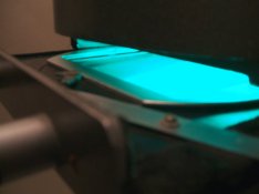
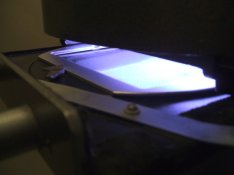
The first print I made was with all three colours (red, green and blue) and all appeared to work well. I was worried about the spread of light and the diffusion not being enough and I was expecting to see the corners lighter than the centre i.e. reduced illumination at the edges. Actually it looks very even across the whole print so I don't think there is anything wrong with the diffusion I have used.

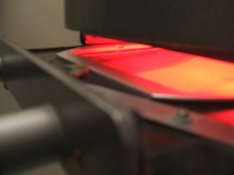
I then tried prints with just the green and just the blue LEDs. Both of these worked very well and showed low and high contrast as expected. Not at the extremes of 0 and 4 or 5 as could be achieved with normal filters but perhaps 1 to 3 or 3.5 (just guessing here).

The thing which surprised me was that for a similarly dense print I needed just over twice the time with green as I did with blue. I was expecting it to be the other way round.

Another surprise was the amount of light. As a guide, printing a 5x4 negative up to 10 x 8 with the lens two stops down, I could get a good print with around five seconds exposure time. I may increase the diffusion a bit to both reduce the level and to be sure of good light spread (even though I have already stated that it is ok!).

I will update this thread with some pictures when I get them.


Steve.
 
Thanks for the update Steve. I was wondering about this very thing last night, and if the lens was working out for you.
 
The lens is working fine thanks. Did those small, rectangular pieces of paper turn up in the post?


Steve.
 
Oh my, yes they did. I converted them into liquid refreshment, as you said they would.

cheers
 
They were useful beer tokens at that. They were accepted at the local watering hole.
Worker, I did that too. My mom wasn't real happy with me for a while.
 
I think the technical term is "Beer Tokens", but I could be wrong.:smile:

I think I did refer to them as beer tokens in my covering letter!


Steve.
 
Yes Steve, you did refer to them as "beer tokens".
 
The thing which surprised me was that for a similarly dense print I needed just over twice the time with green as I did with blue. I was expecting it to be the other way round.

Someone on another forum has pointed out that I shouldn't be surprised by this as the nature of the blue sensitive higher contrast emulsion should build up density quicker than that activated by green light. For a fair test I should compare the times taken to get to a mid grey.

The next step is to get some new fixer and make some proper prints and lots of notes - something I don't often do but should!

I am then going to work on a switch mode controller with a single control so that fully anti-clockwise the duty cycle is 100% green and 0% blue. Turning the control clockwise will increase the duty cycle of the blue and reduce that of the green so at the mid point they both receive 50% and fully clockwise it is 0% green and 100% blue. This will give me a single Contrast control. I may also add an overal Brightness control. All I need to add are Horizontal and Vertical Hold controls and it will resemble a 1960s TV!


Steve.
 
All I need to add are Horizontal and Vertical Hold controls and it will resemble a 1960s TV!


Steve.[/QUOTE]

And your dad sitting in his favorite easy chair directing you how to adjust the thing, and "change that channel, I dont like what you're watching!"
 
All I need to add are Horizontal and Vertical Hold controls and it will resemble a 1960s TV!

Oh, come on---this is the 21st century; you should at least come into the 1970s and add a wired remote control :smile:
 
Keep working on it Steve, it's a fresh breath of hope in light of the Aristo demise, I know I'm following your work with great interest. Maybe when you are ready a photo of it would be nice.
 
Here are the pictures I have made so far:


Steve.
 

Attachments

  • DSCF0387.JPG
    DSCF0387.JPG
    1.2 MB · Views: 210
  • DSCF0388.JPG
    DSCF0388.JPG
    1.2 MB · Views: 175
  • DSCF0389.JPG
    DSCF0389.JPG
    1.2 MB · Views: 169
  • DSCF0390.JPG
    DSCF0390.JPG
    119.1 KB · Views: 203
Well done, Steve!

So you balance contrast by altering how many green and how many blue diodes are illuminated?

It's great to be able to focus with green light also, because that's the color our eyes are the most sensitive to.

Forgive my ignorance, but what are the red LEDs for?

Thanks,

- Thomas
 
Steve,

How handy are you with electronic circuit building?
Can you make a pulse width modulation circuit to control the brightness of the LEDs?

You don't want to try to vary the brightness of the LEDs with pure resistance because they are not voltage driven devices, they are current driven devices. If you try to use a potentiometer you won't get a linear response out of them. You'll drop the voltage below the forward threshold of the LED and it will just peter out on you.

Instead, vary the length of time each LED is lit by minute amounts. Do this and you will have very precise control of the mixture of red, green and blue light emitted by your array.

And, in turn, you might get a very interesting method of contrast control from your enlarger which is operationally similar to dialing in contrast settings on a diachronic color head.

Here is an example of the PWM control I am talking about for LEDs.
http://www.robotroom.com/PWM4.html
(Just the first part at the top of the page.)
 
It that a 74AC14 Hex Schmitt-Trigger Inverter? Do each LED have a separate circuit or can they be group in Red, Green, Blue etc.?

If the light is right then control is the problem to be solved. Thanks for the photos Steve.
 
Making your own PWM circuit is a valid exercise, but LED drivers are pretty cheap and available. I bought a digitally regulated, multi-mode driver board for a homemade flashlight on Dealextreme.com for $1.63 with free shipping. So there are probably ready-to-go PWM led drivers available, especially with LED becoming more popular for household lighting.
 
(re: red LEDs)

They could be used as a safelight for aligning paper etc, like enlargers which have a red filter which can be put beneath the lens...

I'm not the one who designed and built it, but if they're the right color (and if the blue and green LEDs are the right color), the whole setup could be used for color printing, too. This would be conceptually very similar to a Philips Tri-One enlarger, which uses halogen bulbs behind red, green, and blue filters to provide light for VC B&W and color printing. I've got one of the Philips machines and it works quite well.

How safe are they Steve? (and where can these be had inexpensively :tongue: )

I don't know about the LEDs that Steve used, but I've got a red LED safelight above my darkroom's wet side. It's bright, compared to other safelights I've used, and safe out to at least several minutes. (I don't recall the limits of my tests, but it was probably at least five minutes.) Of course, the intensity may be less than what would be projected by a red LED light source in an enlarger....
 
It that a 74AC14 Hex Schmitt-Trigger Inverter?

Curt;

Yes, it is an inverter. I did Google this page but that's why I picked it... because it was what I remembered using in Vo-Tech classes all those years ago. I did not specifically remember the Schmitt trigger inverter but I did remember that there was an RC circuit that you could use to make PWM that used a certain inverter chip. It was only partly from memory but mostly from looking it up.

Making your own PWM circuit is a valid exercise, but LED drivers are pretty cheap and available. I bought a digitally regulated, multi-mode driver board for a homemade flashlight on Dealextreme.com for $1.63 with free shipping. So there are probably ready-to-go PWM led drivers available, especially with LED becoming more popular for household lighting.

Better Sense;

You're right. There probably is an IC that does it all for you but this is the way I think. If you can find such an animal there's no reason not to use it.

You're talking to the guy who spent the better part of a weekend aligning his enlarger to within 140 microns. How else do you think I'd go about it?
:wink: :wink: :wink:
:D
 
Thanks, how do you align the enlarger to the precision of 140 microns? If I can find a better way I won't go wandering at night and be consumed by fire.
 
It was a joke. It was in another message thread where I was talking about the amount of leeway one has when focusing. It was all theoretical, really, but Better Sense said that I have better things to do than count the number of microns within which I can focus my enlarger. It was all good natured banter, actually, even though he was right. (And, I did just go make some prints. :wink: )

So, the point was that he caught me, once again, behaving somewhere in the territory between "anal retentive" and "O.C.D." :wink:

The bottom line is that I built my electronic circuit out of an IC and several discrete components where Better Sense advises that there might be a monolithic solution to the problem. He's probably right and I agree it would be a better solution if it were not my tenancy to do everything the hard way. :wink:

BTW: In over four years of using that conundrum in my signature line you are one of only two people have said that they understand it. (Or, at least, people who have admitted to understanding it. :wink: )
 
(re: red LEDs)
I'm not the one who designed and built it, but if they're the right color (and if the blue and green LEDs are the right color), the whole setup could be used for color printing, too. This would be conceptually very similar to a Philips Tri-One enlarger, which uses halogen bulbs behind red, green, and blue filters to provide light for VC B&W and color printing. I've got one of the Philips machines and it works quite well.
Of course it could :smile: I plan to make a 'graflarger style' back with LEDs for just this purpose.
 
So you balance contrast by altering how many green and how many blue diodes are illuminated?

It's great to be able to focus with green light also, because that's the color our eyes are the most sensitive to.

Forgive my ignorance, but what are the red LEDs for?

The contrast is balanced by the relative times the blue and green LEDs are on. It has red LEDs because it uses the PCB from an LED stage light. The red is useful for checking the easel alignment or for working out where to dodge or burn a bit like the red filter on some standard enlargers.


Steve.
 
Photrio.com contains affiliate links to products. We may receive a commission for purchases made through these links.
To read our full affiliate disclosure statement please click Here.

PHOTRIO PARTNERS EQUALLY FUNDING OUR COMMUNITY:


Ilford ADOX Freestyle Photographic Stearman Press Weldon Color Lab Blue Moon Camera & Machine
Top Bottom