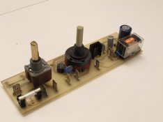
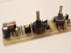
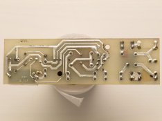
Jobo Resistor

Roses

A
Roses

  • 2
  • 0
  • 55
Rebel

A
Rebel

  • 4
  • 2
  • 69
Watch That First Step

A
Watch That First Step

  • 1
  • 0
  • 58
Barn Curves

A
Barn Curves

  • 2
  • 1
  • 52
Columbus Architectural Detail

A
Columbus Architectural Detail

  • 4
  • 2
  • 54

Forum statistics

Threads
197,488
Messages
2,759,835
Members
99,515
Latest member
falc
Recent bookmarks
9

Thiago Lara

Member
Joined
May 29, 2010
Messages
9
Location
São Paulo -
Format
Medium Format
Hi, Apugers!

Bought this CPE-2 on fleaBay some months ago to backup my CPA-2. It came with the motor somehow slow... you can see in the video below:

http://www.youtube.com/watch?v=kJvExXiq3jY

I'm in Brazil, and it came from US. So just the shipping to receive it was almost the same value of the processor, sending it back would only make me loose more money, so was not an option. Didn't bother to contact the seller, since the guy basically sent me his trash, it's hard to believe that he didn't knew the processor was defective. After months trying to find someone to service it here, I decided to try it myself. Found a blinking toasted resistor in the control board, it blinks when the motor inverts:

[video=youtube;QKFbIQ0Zp8M]http://www.youtube.com/watch?v=QKFbIQ0Zp8M[/video]

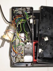
Here's a picture of the board of my processor:
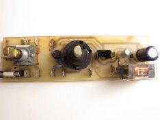
IMG_0902_2.jpg

The problem is that I can't identify the resistor by the stripes, I think the former owner has insisted in using it this way during some time, the thing is really toasted, it's gray:
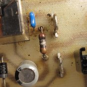
IMG_0919_2.jpg

I find the picture below on the internet, this guy has changed the whole board in order to keep the high voltage on the lower speed setting and keep the torque high... another thing, but there's a picture of the original board there... unfortunately it's black and white.

jobo_orig.GIF


here:http://www.tech-diy.com/Photography/JOBO CPE2 Motor Speed Controller/jobo.htm

Would some lovable owner of a CPE-2 here make me the huge favor of opening the panel of the processor to identify the resistor, so I can try to find one to replace it? This things are identified by the number of the stripes and it's colors, I'm informing myself about it as I research a solution for this machine, I know nothing on electronics, so a picture would be great. But I understand that people here doesn't have digital cameras – I've actually thinking on selling all my digital crap everyday since I started with film – so if a picture it's not possible just a identification on the colors of the stripes on it will be fine as well.

And since I'm already asking, I would love to know more about resistors and this specific problem. What could have caused it? I read thats usually caused by an overload, but what can be the cause for this overload? A subtle variation in the power? Plugin a 110v machine in a 220v wall socket? I'm wondering if it's something external or another component in the machine which may be the real cause for this toasted resistor. What do you think?

Thank you very much,

Thiago Lara.
 

ic-racer

Member
Joined
Feb 25, 2007
Messages
16,484
Location
USA
Format
Multi Format
This is a guess based on the pictures, Brown, Black, Orange, Gold = 10k 5% Carbon film resistor.

There are others on this forum (like Gregg Blank) that can give an exact answer.
 

ath

Member
Joined
Aug 29, 2006
Messages
844
Location
Germany
Format
35mm
Most probably the resistor gets overloaded because something else is wrong. Changing the resistor alone will probably not cure the problem. Maybe the motor is the problem.
You might want to contact the Jobo Analog service in Germany and ask for a replacement board or they might give you the schematic and someone with electronic skills repairs your board.
 

Diapositivo

Subscriber
Joined
Nov 1, 2009
Messages
3,257
Location
Rome, Italy
Format
35mm
I have the Jobo CPP-2 Service Manual.

I don't know which are the differences between CPP-2 and CPA-2 but it can be of help. Plenty of electric schemes.

I tried to attach it to this post but the operation does not work.

I'll try later, or I can send it to anybody requesting it if they send me their email via private message.

Fabrizio
 

EdoNork

Member
Joined
Mar 15, 2010
Messages
69
Location
Bilbao
Format
Multi Format
Hi Fabrizio, can you post the service manual somewhere?
Thanks.
 

Nicholas Lindan

Advertiser
Advertiser
Joined
Sep 2, 2006
Messages
4,215
Location
Cleveland, Ohio
Format
Multi Format
You can't tell the value from the supplied picture. And gold doesn't always mean 5%.

Some designs use resistors as very slo-blo fuses - never a good idea. But that does look like the case here - with the posts holding the resistor away from the board so that when it flames it doesn't set the board on fire. The resistor may unplug from the posts for easy change out.

If the resistor was associated with motor current limiting then it may have blown if the motor stalled out or was run with a heavier than expected load from a gummed gearbox or some such.
 

Steve Smith

Member
Joined
May 3, 2006
Messages
9,110
Location
Ryde, Isle o
Format
Medium Format
Does the unit still work properly despite the sparking resistor?

The reason for asking is that judging from the close up picture, the resistor appears to be connected in series with the blue capacitor above it. If this is the case, it could be possible that the capacitor and resistor form a 'snubber network' which is connected across the motor connections.

The unit will work fine without it as the purpose of a snubber network is to reduce electromagnetic interference from electrical contacts - in this case, the brushes and armature connections of the motor.

If this is the case, the most common value for the resistor is 100 ohms (with a 0.1uF/100nF capacitor).


Steve.
 

Nicholas Lindan

Advertiser
Advertiser
Joined
Sep 2, 2006
Messages
4,215
Location
Cleveland, Ohio
Format
Multi Format
Looking at the video, Steve may be right -- it is a snubber across the motor. [When you said 'sparking' I thought it was in reference to the resistor being burned, not that it was actually sparking - they don't usually spark (or not for long)...] The snubber isn't there for EMI but to absorb the inductive kick when the motor reverses - well, there will be a burst of EMI from the relay contacts at reversal and it will help with brush noise but brush noise caps are usually right at the motor terminals. You can see the spark when the relay clicks and the motor 'whines in the other direction', though it only sparks on one of the two reversals. It could be the relay contacts are absorbing the spark in the other direction.

The 100 ohm/.01 standard snubber is used for 110/220V AC circuits. It is my understanding the Jobo motors operate at 24V. The snubber resistor shouldn't have blown. OTOH, why a snubber should be up on spacers like that is a bit of a mystery. It is possible the capacitor shorted out, and that is what caused the resistor to burn/open. As it is a small cap the chances are the voltage rating is rather low. Try replacing the resistor with a 100 ohm 1/2W [a good a value as any?] and the cap with the same value but with a 200V or more voltage rating. The standard snubber capacitor is Dead Link Removed - but it is for 110/220 circuits.

The busted snubber circuit won't be the reason the motor turns slowly, though. The resistor is open - if it were still good there would be no spark and in any case it takes no current from the motor.

You should replace the snubber, though, or you will soon find yourself needing a new relay. The snubber keeps the relay contacts from pitting.
 
OP
OP
Thiago Lara

Thiago Lara

Member
Joined
May 29, 2010
Messages
9
Location
São Paulo -
Format
Medium Format
Wow! That's a wonderful feedback. Thank you all very much!

Thanks for the info on the German guys, ath! I'll contact them soon. Right now I'm waiting a response from a US guy on the spare parts, lets see what's he gonna tell me first, since the shipping will be cheaper from US. Also, I already bought some itens from this guy that I'm waiting a response in the past, nice guy.

Diapositivo, you're always saving me! Thank you very much. At this point any info will be worthwhile, since I'm already looking for alternatives for the board and the motor. I'll send you a PM.

polyglot, I just googled (jobo motor hoffy site:apug.org) and found lots of information on this exactly same issue. Thank you very much for the reference, I wasn't found those threads on my earlier search. References to several repairs and modifications on a dead CPE-2.

Hoffy's threads:

(there was a url link here which no longer exists)

(there was a url link here which no longer exists)

Other threads that may be useful here, still researching:

(there was a url link here which no longer exists)

(there was a url link here which no longer exists)

I'll try call Hoffy and also Gregg Blank that ic-racer said here in this thread through PMs.

Right now I think my best bet would be try to improvise some 24V input and try the motor alone to see what happens, right? Something like 3x 9v batteries (27V?) in series would do it? I also have a pair of 12V 5Ah batteries from a portable flash unit, if I wire them in series it would be 24V 5Ah, right? Can I test the motor with that? What do you think?

About the controller board... I seeing that will be my real headache. Steve Smith and Nicholas Lindan, I think I'm failing in following you two here. Here's some more detailed pictures of the board:

IMG_0938_2.jpg

IMG_0941_2.jpg

IMG_0937_2.jpg

IMG_0934_2.jpg IMG_0934_2.jpg

Whats exactly the components you think I need to replace? Do you think I also need to replace the motor?

Here's a video on the motor and it's noises, and some pictures so you can check if everything is wired the right way in the right places... the machine seem like was serviced before, some wear from instruments on the bolts, things like that... maybe its wrong connected somewhere, I don't know:

[video=youtube;ajE6V2OfFfA]http://www.youtube.com/watch?v=ajE6V2OfFfA[/video]

IMG_0926_2.jpg

IMG_0931_2.jpg

IMG_0930_2.jpg

IMG_0922_2.jpg

Thank you all very much for your inputs so far. Hoping to hear more! :smile:
 

Diapositivo

Subscriber
Joined
Nov 1, 2009
Messages
3,257
Location
Rome, Italy
Format
35mm
Know nothing of electronics but I see a sparkle, in the first video, at each engine rotation reverse. I don't know if it is normal.

Also, be careful not to let the pump or heater work without water during the tests. Actually I wouldn't let the motor itself run without water in the upper basin.
 

ath

Member
Joined
Aug 29, 2006
Messages
844
Location
Germany
Format
35mm
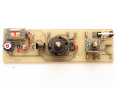
Components 2 and 3 are the snubber network which protects the contacts of the relay 1. Probably the capacitor 2 has developed a short exposing the rather low ohmic resistor 3 to the supply voltage. The resistor got overloaded and toasted (opened). This effectively deactivated the snubber and every reverse of the motor generates high voltages which in turn generate the arcs we saw in your video.

components to change: 2 and 3
probably a good idea to change the relay as well.
If the motor is ok, well, we will see.
 

Steve Smith

Member
Joined
May 3, 2006
Messages
9,110
Location
Ryde, Isle o
Format
Medium Format
Steve Smith and Nicholas Lindan, I think I'm failing in following you two here. Here's some more detailed pictures of the board:......…

Whats exactly the components you think I need to replace? Do you think I also need to replace the motor?

Replace the resistor with another resistor of about 100 ohms rated at 1/2 watt. Also replace the little blue capacitor next to it with a capacitor 0.1uF or 100nF (same value, just two different methods of specifying) rated at 250v or 400v.

No need to change the relay or motor yet, just see if this sorts it out.


Steve.
 
OP
OP
Thiago Lara

Thiago Lara

Member
Joined
May 29, 2010
Messages
9
Location
São Paulo -
Format
Medium Format
Thank you very much!

Fabrizio, this unit is smaller than a CPA, it doesn't have a pump or a upper basin. In these CPE units the water sits in only one compartment with the heater, the bottles and the tank. It's the movement provided by the tank which moves the water around.

ath and Steve Smith, thank you very much. Here in São Paulo there's this street called Santa Efigênia, where there several vendors of this kind of component. So I'll try my luck on finding them locally tomorrow, as long as a solder iron. Or maybe I can get real lucky and find someone professional to do the job for me, lets see. :D

About testing the motor with another supply... do you think that 3x 9v regular batteries or the 2x 12v 5Ah flash batteries in series would do it as a test supply? And where should I wire it to the motor? Which one is the (-) and the (+)? Can you point the numbers on the picture for me? I know its a pretty monkeyish way to ask this kind of thing but I'm really lost here.

IMG_0926_3.jpg

Thank you very much. :smile:
 
Last edited by a moderator:

Steve Smith

Member
Joined
May 3, 2006
Messages
9,110
Location
Ryde, Isle o
Format
Medium Format
That video is fine but for a small PCB like yours which is removed from the unit, my method is to apply the soldering iron to the joint until the solder melts then turn the board over and tap it on the workbench. This shakes off most of the solder from the wire of the component. Do the same for the other end and the component should then be loose.

The PCB is single sided so you don't need to worry about removing solder from within plated through holes but because it is single sided, it is more susceptible to heat damage so do not apply the soldering iron for longer than is necessary or you could melt the glue which holds the copper to the base material.

Don't let this put you off though, it's easier to do than it is to write about doing it!

As for the motor, wires 1 and 2 are the motor connections, 3 is a ground/earth connection. Two 9v batteries in series should be enough to see if it works whilst it's not physically connected to the rest of the mechanism. In fact, one on its own will probably turn it.

It doesn't matter which one is + or - as if you connect it one way round it will turn clockwise and if you swap the wires over it will turn anticlockwise.


Steve.
 
Last edited by a moderator:

Nicholas Lindan

Advertiser
Advertiser
Joined
Sep 2, 2006
Messages
4,215
Location
Cleveland, Ohio
Format
Multi Format
If you are removing a dead component - and the resistor is very dead, the cap is presumed so - the best way is:

  • Cut the component in two with a pair of cutters
  • Hold the board vertically in a vise
  • Grip one wire of the component with a pair of pliers [on the component side of the board]
  • Apply the soldering iron to where the wire solders to the board [on the solder side]
  • Pull the wire out when the solder melts

If you apply the iron for too long then the conducting foil will come unstuck from the board. That's why the cut and crush technique above is preferred - it minimizes the chance of damaging the board.

Don't try pulling the component out with your fingers while applying the iron - you will burn your fingers, and the component will still be in the circuit board. It works for big parts, not small one.

If the hole is clogged with solder then the toothpick trick in the video isn't a bad way to unclog them.

Before doing any [un]soldering, try pulling on the leads of the burned resistor and see if they just slip out of the posts. If they do then clip and bend the leads of the new resistor and push them into the posts.
 
Last edited by a moderator:

Sirius Glass

Subscriber
Joined
Jan 18, 2007
Messages
50,135
Location
Southern California
Format
Multi Format
If you are removing a dead component ...

If the hole is clogged with solder then you may as well get crude: melt the solder with the iron and thwack the board on the bench so the solder flies off. Don't thwack too hard ...

BETTER go to Radio Shack or other electronic component store and buy either
  • a "solder sucker" which is a suction bulb with a long conical tube ==> heat the solder, squeeze the air out of the bulb, apply the end of the tube to the solder and let the bulb expand quickly
Dead Link Removed or
combined with soldering iron Dead Link Removed

  • or a "solder wick" which is metal braid ==> put the braid on the solder, heat the braid and the solder, the braid will draw up the solder.
Dead Link Removed


Let us know what you did and how it worked.

Steve
 

Steve Smith

Member
Joined
May 3, 2006
Messages
9,110
Location
Ryde, Isle o
Format
Medium Format
De-soldering braid and solder suckers can work well but for a single sided, non pth board, I don't think they are worth the trouble - especially as the OP is probably only going to use them for these two components. I like Nicholas' cut the component in half method although I think the resistor has already done that by itself!


Steve.
 

MattKing

Moderator
Moderator
Joined
Apr 24, 2005
Messages
51,947
Location
Delta, BC Canada
Format
Medium Format
I think it worthwhile to congratulate the OP for at least one thing - this has to be one of the best illustrated examples I have ever seen of a "this is my problem, can you help me with it please" threads.
 

Sirius Glass

Subscriber
Joined
Jan 18, 2007
Messages
50,135
Location
Southern California
Format
Multi Format
At that price the OP could order the whole board shipped from overseas.
 

ic-racer

Member
Joined
Feb 25, 2007
Messages
16,484
Location
USA
Format
Multi Format
I bought a Durst with a similar problem involving a resistor snubber for a relay. This one was for the Durst CLS2000 shutter motor. I replaced the fried components and it has been fine ever since.

DSCF4768.jpg
 
OP
OP
Thiago Lara

Thiago Lara

Member
Joined
May 29, 2010
Messages
9
Location
São Paulo -
Format
Medium Format
WOOHOO!!!

Dead Link Removed

[video=youtube;jxIPP2F5BBM]http://www.youtube.com/watch?v=jxIPP2F5BBM[/video]

So, it was the motor. I managed to test it with a different supply, and got the same noise and everything.

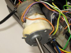
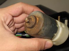
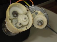
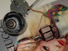
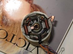
Since I already had found a spare motor to buy on a reasonable price, having nothing to loose, and inspired by Hoffy's threads already mentioned here, I decided to open the motor:

IMG_0944_2.jpg

IMG_0945_2.jpg

It was very dirty inside... This processor looks like it was burried, go figure! Anyway, I dismantled everything was possible, cleaned, closed, and it worked!

:D

The led flickering was just... the led, broken wire. The motor is running close to 60 rpm, maybe something like 55 rpm, but it does get a little slower when the heater clicks on as you can see in the video. I don't think it's anything significant, tough. Just asking: Do you know if is that normal on the CPE? My CPA doesn't do that.

The sparkling resistor keeps sparkling, although not that often. It sparkles once each 5 to 8 inversions. Anyway, I've already found the components locally here and I'm planning to do the repair. But I'm getting just a little afraid of doing it, since the thing is now working. Do you think this board repair is really a must? I mean, do you think the processor will work any better after the repair, or can it be damaged again for not doing it?

Replace the resistor with another resistor of about 100 ohms rated at 1/2 watt. Also replace the little blue capacitor next to it with a capacitor 0.1uF or 100nF (same value, just two different methods of specifying) rated at 250v or 400v.

No need to change the relay or motor yet, just see if this sorts it out.


Steve.

Hey Steve, you were the only one wich provided me specific data about the components, so I'm on your recipe here. Would you please check if I'm getting the proper components?

I think I got the proper resistor, 1/2 watt, in this case the "100 ohms" would be the "100R" option in the link below, right?

http://loja.multcomercial.com.br/ecommerce_site/produto_5666_4689_Resistor-Filme-Metalico-SFR25H-1-2W-Minimo-10-pecas

But for the capacitor, I found several options that would fit the "description"... as far as I could get, "nF" is the same as "kpF", right?

Here's one 100K/400V and 100K/250V:
http://loja.multcomercial.com.br/ecommerce_site/produto_5251_4689_Capacitor-Poliester-Serie-B32591-Epcos

Here's one 100K/250VAC (AC? is it different than just "V"?):
http://loja.multcomercial.com.br/ecommerce_site/produto_5252_4689_Capacitor-Poliester-Serie-B81192-Epcos

And also this one, but by the picture it looks a little different from the one in my board:
http://loja.multcomercial.com.br/ecommerce_site/produto_5247_4689_Capacitor-Poliester-Serie-B32529-Epcos

Which one should I get? Also, I didn't mentioned before, my processor is 110V, I don't know if there's any difference... Since I'm seeing 250v and 400v on the capacitors... just mentioning.

I imagine there's a certain direction for the components on the board. How should I identify it on the components?

Also, thank you very much from all your inputs on soldering. I have no experience on dealing with electronics or soldering at all, so all the scenarios and experiences you shared will be taken into consideration when dealing with the procedure.

Thank you very much so far, Apug! :smile:
 
Last edited by a moderator:

Steve Smith

Member
Joined
May 3, 2006
Messages
9,110
Location
Ryde, Isle o
Format
Medium Format
The resistor is fine and I would use either of the frst two capacitors. Your supplier uses a different marking system to what I would consider normal so get the one marked 100KpF as I assume that is 100nF.

It doesn't matter which way round you put them in.


Steve.
 
Photrio.com contains affiliate links to products. We may receive a commission for purchases made through these links.
To read our full affiliate disclosure statement please click Here.

PHOTRIO PARTNERS EQUALLY FUNDING OUR COMMUNITY:


Ilford ADOX Freestyle Photographic Stearman Press Weldon Color Lab Blue Moon Camera & Machine
Top Bottom