ILEX SHUTTER QUERIES

Field #6

D
Field #6

  • 1
  • 0
  • 12
Hosta

A
Hosta

  • 3
  • 0
  • 19
Water Orchids

A
Water Orchids

  • 1
  • 0
  • 18
Life Ring

A
Life Ring

  • 1
  • 0
  • 20
Fisherman's Rest

A
Fisherman's Rest

  • 7
  • 2
  • 56

Recent Classifieds

Forum statistics

Threads
197,899
Messages
2,766,604
Members
99,500
Latest member
Neilmark
Recent bookmarks
1
OP
OP

tonyowen

Member
Joined
Nov 21, 2015
Messages
157
Location
Anglesey, UK
Format
Multi Format
Does the plate pivot on the shaft?
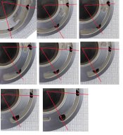
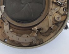
Thank you, yes the plate pivots and the various gear trains move smoothly. The shutter blades open smoothly without jarring or catching.
The spring on the main cocking arm is far lighter than I had expected based upon the descriptions on the Ilex Acme 2 shutter.

I've used cotton buds dipped in Isopropyl Alcohol and rubbed around the various sections, which has cleaned some gunk/dirt off..

If I cannot get the delay pallet off I might pour a small amount of Isopropyl Alcohol into the casing and swill it around..
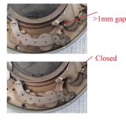
The cable release 'tube' had sprung slightly but I closed that and the cable release no longer slides past the arm.
regards and thanks
Tony
 
OP
OP

tonyowen

Member
Joined
Nov 21, 2015
Messages
157
Location
Anglesey, UK
Format
Multi Format
Hi Shutterfinger

Just an update

Spent some time looking for a spring that shot up in the air and was found over 2m away!!!

The B&T mechanism seems not to sit prioperly and wobbles a lot – prior to its spring and screw being fitted.

Following a partial dismantling and cleaning – I could not get the delay pallet off and didn’t want to risk damaging things – I did some speed checks without the B&T mecahnism being fitted.

For 1s thru 1/150s I got:

0.69s, 0.65s, 0.42s, 1/4s, 0.15s, 0.15s, 1/100s, 0.006s.

I’m assuming the base speed of the shutter is 1s which is then adjusted by the cam movement against pins B & C. Pin A only negating any cam actions of pins B & C, and only relating to the B&T action.

Therefore, if I’m correct, the testing the shutter without the cam will indicate my shutter’s base speed.
If that speed is not 1s, the error is internal. If it is 1s, then the cam tracks need examining.

Comments please

Regards

Tony
 

shutterfinger

Member
Joined
Feb 25, 2013
Messages
5,020
Location
San Jose, Ca.
Format
4x5 Format
B&T may have a shoulder that they sit on or a shoulder screw that holds them, wobbly suggest its not seated properly.
1 second is the base time. If there is no play in the delay timer gearing then the pin operated by the can is bent inward toward the center of the shutter to increase speed, toward the outer edge of the case to decrease speed. The pallet pin can be moved in a similar manner to increase tension on the pallet resulting in slower speeds or to decrease tension to increase speeds. If the delay gearing has play in the screws to mount holes then adjust the delay gearing position to obtain the 1 second.
Standard adjustment, if available, is pallet end of delay gear train for 1 second, front for 1/25, operating pin for fastest speed. It takes a delicate balance and settle for a happy medium of all speeds overall.
When bending the operating pins grip with a pair of small needle nose pliers and move the pin at or close to its base not the center or top. Usually .1mm maximum movement is all that is necessary.
 
OP
OP

tonyowen

Member
Joined
Nov 21, 2015
Messages
157
Location
Anglesey, UK
Format
Multi Format
[QUOTE="shutterfinger, post: 2046172, member: 62550. Usually .1mm maximum movement is all that is necessary.[/QUOTE]
For clarity Is that 1mm or 0.1mm
regards
Tony
 
OP
OP

tonyowen

Member
Joined
Nov 21, 2015
Messages
157
Location
Anglesey, UK
Format
Multi Format
Standard adjustment, if available, is pallet end of delay gear train for 1 second, front for 1/25, operating pin for fastest speed.
Forgot to ask on my earlier email - how would I recognise this feature if it exists on my shutter?
regards
Tony
 

shutterfinger

Member
Joined
Feb 25, 2013
Messages
5,020
Location
San Jose, Ca.
Format
4x5 Format
That's 0.1mm.
Loosen the delay gearing mount screws, one at each end of the gear train, 1 1/2 turns max and check how much movement there is. Some shutters have a slot others the hole the screw goes through is 50% larger than the screw while others it is 25% larger.
I took a closer look at the picture of your shutter, delay gearing screws appear to be countersunk which means no movement.
 
Last edited:
OP
OP

tonyowen

Member
Joined
Nov 21, 2015
Messages
157
Location
Anglesey, UK
Format
Multi Format
That's 0.1mm
Hi
I think I’ve found the problem, but do not know the cure.
One of the attachments shows the relationship between pins B & C and the cam profile. Starting at 1/150s (top left hand corner) down to 1s (bottom left hand corner).
On this image it can be seen that pin C is not in contact with its cam profile at the 1s position.

The second image shows the gear train and delay pallet area. The top pic shows the gear train at rest after activation. As can be seen there is a gap between pin C and the edge of the delay pallet.
The lower pic shows that after slight finger pressure, pin C moves into contact with the edge of the delay pallet.

It seems as though the spring return of the gear train is worn or stuck in some way OR is too weak for the correct action.

Any comments?

Regards

Tony
 

Attachments

  • composite01.jpg
    composite01.jpg
    827 KB · Views: 116
  • pinCproblem03.jpg
    pinCproblem03.jpg
    442.3 KB · Views: 141

shutterfinger

Member
Joined
Feb 25, 2013
Messages
5,020
Location
San Jose, Ca.
Format
4x5 Format
Take the delay gear train out of the shutter, clean all the parts in solvent, put a straight pin point drop of light weight machine oil on the pivots of each gear, reassemble and check. Increase spring tension by increasing the angle between the arms with the spring disengaged. Do not bent the spring arm but hold one side with needle nose pliers while pulling the other out at the base curvature. Each minute mark on a watch is 6°, 3° to 5° should be sufficient then reinstall the spring and check if needed.

This is a classic dirty gear train not running smoothly.
 
OP
OP

tonyowen

Member
Joined
Nov 21, 2015
Messages
157
Location
Anglesey, UK
Format
Multi Format
Dear Shutterfinger

Sometime has passed since we last communicated, but I eventually took the whole ILEX3 shutter to pieces.

Noticeable there was no blade retaining cover [images bitsandpieces] – but whether this is peculiar to other ILEX shutters I do not know

In addition, to my embarrasement, when I ‘opened’ the delay timing assembly [image geartrain] everything fell out so I do not know where the spring fits [Image gears01] as it does not match your image [#2 delay gearing]

1] Should the Ilex#3 have a blade retaining cover – presently the blades are prevented from falling off the pins by the gap between the inside face of the main housing and the bottom face of the disc that holds all of the levers etc.

2] Can you tell me where the spring shown in gears01 fits?

3] The Ilex 3 delay timing assembly seems to have an escapement mechanism the two items to the left of image Gears01 – Please clarify if possible.

Regards

Tony
 

Attachments

  • #2 delay gearing.jpg
    #2 delay gearing.jpg
    3.2 KB · Views: 94
  • bitsand pieces.jpg
    bitsand pieces.jpg
    193 KB · Views: 110
  • gears01.jpg
    gears01.jpg
    822.2 KB · Views: 110
  • geartrain.jpg
    geartrain.jpg
    121.7 KB · Views: 93
OP
OP

tonyowen

Member
Joined
Nov 21, 2015
Messages
157
Location
Anglesey, UK
Format
Multi Format
[QUOTE="shutterfinger, post: 2172881, member: 62550][/QUOTE]
"Thanks for the effort by laptop, touch pad and muscle spasms.
But the spring I mentioned [shown above your item 3] fits somehow below the gears, the one you've drawn fits on top of item 5 and is a different spring
By zooming in image geartrain, the hook end of the spring in question can be [just] seen in the hole of your item 4. I wonder therefore the spring 'rotational centre' fits below the spindle of your item 5.

It is the circular blade retainer cover that is either not part of, or missing from, the Ilex 3 shutter NOT the pentagonal blade/controller retainer.

I'm still at a loss as to understand how the gear train assembly controls the shutter speed. There more gears than necessary and why the escapement - your items 1 and 2?

I look forward to your observations

regards
Tony
 

shutterfinger

Member
Joined
Feb 25, 2013
Messages
5,020
Location
San Jose, Ca.
Format
4x5 Format
Post a much larger image of the gear train as I cannot see ........
The hexagonal plate holds the blade controller and blades in place, the circular plate protects the assembly.
The delay gearing at full travel should run 1 second. By varying the tension on the escapement and the degree of the gear engagement allows for the various speeds.
 
OP
OP

tonyowen

Member
Joined
Nov 21, 2015
Messages
157
Location
Anglesey, UK
Format
Multi Format
Post a much larger image of the gear train as I cannot see ........
The hexagonal plate holds the blade controller and blades in place, .
image biggeartrain attached with arrow 'aimed' at what seems to be part of a hair spring
So, the blades need to BEHIND the pentagonal [5 not 6 sided] plate.
Dismantling that assembly might show reasons for erratic speeds.
Regards
Tony
biggeartrain.jpg
 
OP
OP

tonyowen

Member
Joined
Nov 21, 2015
Messages
157
Location
Anglesey, UK
Format
Multi Format
A postscript I've been meaning to mention is that the shutter blades are not rubber, but metal - or contain an inner metal structure - since they are magnetic ie can be picked up with a magnet
regards
Tony
 
OP
OP

tonyowen

Member
Joined
Nov 21, 2015
Messages
157
Location
Anglesey, UK
Format
Multi Format
campic.jpg
Now a picture of the other side of the gears and the under side of the gear train top, please..
What do you mean 'the other side of the gears'/

I've done some analysis of pins B and C regarding measured speed:-

Cam follower pin C moves outwards and cam follower pin B moves inwards as the speed setting changes from 1s to 1/150s.

Using GIMP2’s ‘measure tool’ and the png version of the attached image I was able to measure the radial distance to the inner and outer cams at the marked 12 points. [For some reason I am unable to upload the png file.]

The inner cam moves pin C outwards until the 1/25s position, but then remains in the same or a lesser radius as the speed selector is advanced.

Coincidentally pin B ‘appears’ to come into contact with the outer cam at the 1/25s position and then moves inwards until the 1/150s position is reached.

My inability to ‘get’ 1/25s and 1/50s speeds infers that pin B is not moved far enough inwards at positions I and J. The 1/100s speed is ambiguous in terms of my determination of shutter speeds.

regards
Tony
 

shutterfinger

Member
Joined
Feb 25, 2013
Messages
5,020
Location
San Jose, Ca.
Format
4x5 Format
What do you mean 'the other side of the gears'/
I was referring to gears01.jpg in post 35. Appears you figured out where the spring went and reassembled the delay gear train.

Now to address the speeds issue. These shutters ran correct when new. Springs weaken with age and usage, cam edges wear down. A few thousands wear on a cam can make a big difference. That speed selector/ cam plate should be perfectly flat against the top cover, if not correct.
A common speed adjustment is to either swedge or file at a specific speed position. Swedgeing is taking the cam or speed ring, laying it on a flat solid surface and tapping the area with a hammer and punch usually about 1 or 2 millimeters behind the edge so as not to deform the edge. A .001 inch/.0254mm can make a big difference in a speed.

It has been my experience to adjust for overall accuracy of the speed range in place of trying to get each speed perfect. Sometimes a speed will be off at the marked point but correct the indicator line one side or the other from the marked point.
 
OP
OP

tonyowen

Member
Joined
Nov 21, 2015
Messages
157
Location
Anglesey, UK
Format
Multi Format
A few thousands wear on a cam can make a big difference. That speed selector/ cam plate should be perfectly flat against the top cover, if not correct.A common speed adjustment is to either swedge or file at a specific speed position. Swedgeing is taking the cam or speed ring, laying it on a flat solid surface and tapping the area with a hammer and punch usually about 1 or 2 millimeters behind the edge so as not to deform the edge. A .001 inch/.0254mm can make a big difference in a speed.
It has been my experience to adjust for overall accuracy of the speed range in place of trying to get each speed perfect. Sometimes a speed will be off at the marked point but correct the indicator line one side or the other from the marked point.

Okay, I agree with your statement which makes sense taking age, usage and materials into account.

So I either stick with what I have got or risk making it better OR WORSE. I''ll test for speeds away from the marked sections.

Regards
Tony
 

shutterfinger

Member
Joined
Feb 25, 2013
Messages
5,020
Location
San Jose, Ca.
Format
4x5 Format
General Rule of Thumb: The delay usually has a little play in the screw hole or its a slot. Adjust the pallet end for accurate/best you can get 1 second. The actuator end varies from manufacturer to manufacturer but is 1/15 or 1/20. Set the 1 second first, the higher speed second then recheck the 1 second. When both hold good test the remaining speeds.
 

MTGseattle

Subscriber
Joined
Dec 8, 2013
Messages
1,363
Location
Seattle
Format
Multi Format
Bump for an old-ish thread.
Does any of the above info apply to an Ilex #5 universal synchro shutter? My speeds are 1,2,5,10,25,50,B and T.
 
Photrio.com contains affiliate links to products. We may receive a commission for purchases made through these links.
To read our full affiliate disclosure statement please click Here.

PHOTRIO PARTNERS EQUALLY FUNDING OUR COMMUNITY:


Ilford ADOX Freestyle Photographic Stearman Press Weldon Color Lab Blue Moon Camera & Machine
Top Bottom