

After mentioning in various threads that 5x4 (or 4x5) enlargers are being given away in the US but command high prices in the UK, I now have one which didn't really cost me any money.
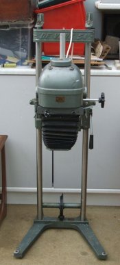
In return for a few spare pieces I had for Mamiya TLRs, I got a Devere 54 with cold cathode light source. I just paid for the postage.
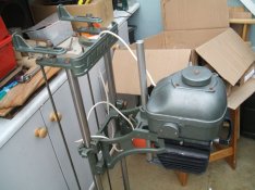
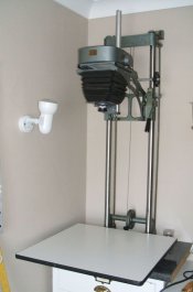
It has been taken apart and delivered in four boxes so I will have a go at putting it back together tonight.
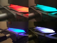
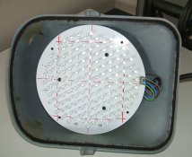
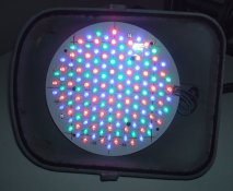
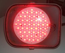
It has been said that the light from the cold cathode source is fairly blue and can be a problem with variable contrast filters so I am planning on building an LED light source for this. I have the PCB from an LED stage light which is fitted with red, green and blue LEDs which I think will work quite well.
Steve.
In return for a few spare pieces I had for Mamiya TLRs, I got a Devere 54 with cold cathode light source. I just paid for the postage.
It has been taken apart and delivered in four boxes so I will have a go at putting it back together tonight.
It has been said that the light from the cold cathode source is fairly blue and can be a problem with variable contrast filters so I am planning on building an LED light source for this. I have the PCB from an LED stage light which is fitted with red, green and blue LEDs which I think will work quite well.
Steve.

 ).
).