How to bypass timer for Omega super chromega D II head?

Scales / jommuhtree

D
Scales / jommuhtree

  • 0
  • 0
  • 2
3 Columns

A
3 Columns

  • 6
  • 7
  • 150
Couples

A
Couples

  • 4
  • 0
  • 113

Recent Classifieds

Forum statistics

Threads
199,062
Messages
2,785,629
Members
99,792
Latest member
sepd123
Recent bookmarks
0

Tigerten

Member
Joined
May 4, 2022
Messages
8
Location
USA
Format
Medium Format
Hello friend

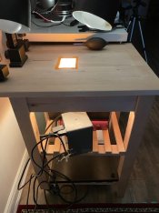
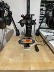
Just bought an Omega Super Chromega DII diachroic head to use as light soirce for digitizing negatives. I have tried LED panels. They are bit too dim.


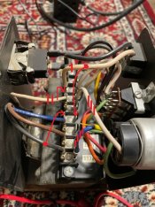
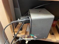
The head comes with a power supply omega 412-021. Other than a special outlet that goes to the head, the head has two outlets, one to the timer and one from the timer. Unfortunately, it does not come with a timer. I don’t actually need a timer for my purpose. I need a continuous light in a short span to avoid over heating.

I don’t really know how the electronics work here. How does timer works here? Can i make a cable to bypass the timer?

The outlet to the timer is supposed to power the timer. What is the voltage? 110v or 24?

Does the timer actually put out 24v to the outlet from the time on the power supply? Or does it just interrupt or connect to the outlet from the timer?

I never used theae stuff before and don’t have any at hand to measure, play or test. I tried to google and can’t find any info in general.

Thanks.
Greg
 

ic-racer

Member
Joined
Feb 25, 2007
Messages
16,556
Location
USA
Format
Multi Format
Power supply manual
 

Attachments

  • Omega Chromega Power supply.pdf
    63.5 KB · Views: 181
OP
OP

Tigerten

Member
Joined
May 4, 2022
Messages
8
Location
USA
Format
Medium Format
Thanks a lot, @ic-racer

This really helps!!

The transformer is expecting 117VAC from the timer, which I am sure is not universal across all timers. Is it okay if I just use wall outlet power (Canadian 120v spec, but I think it is about 123VAC on measurement) to power the transformer? how much will this impact the output voltage? The halogen bulb is rated at 250W and 22.5V.

Thanks

PS: I guess the timer does not really alter the voltage, correct? It will output whatever voltage it is fed from the outlet, correct? If this is the case, I guess I know my answer.

Correct me if i am wrong.

Thanks again

Greg
 
Last edited:

ic-racer

Member
Joined
Feb 25, 2007
Messages
16,556
Location
USA
Format
Multi Format
Yes, power it from the wall to ‘from timer’ socket.
 
Joined
Sep 10, 2002
Messages
3,596
Location
Eugene, Oregon
Format
4x5 Format
Whatever you do, make sure that the cooling fan is operating. I can power the light on my Chromega heads with a separate timer without turning on the main power supply that powers the fan (not really sure why that's wired that way, but I have to make sure that the fan is operating before I switch on the enlarger lamp with the timer!).

Not having the cooling fan when the enlarger lamp is on for longer periods can result in overheating and damage.

Best,

Doremus
 
OP
OP

Tigerten

Member
Joined
May 4, 2022
Messages
8
Location
USA
Format
Medium Format
It is very easy. Just want to share What I did, esp. for those wanting to accomplish the same. By the way, the enlarger head is perfect as light source to digitize negative. It is much brighter than any LED panel and it is very even and color acurate being a halogen bulb.

The table is an Ikea kitchen cart, bought for $25 used. I bought the color head and power supply for $40. I mounted the copy stand column onto it, then cut a rectangle hole right underneath the lens.

The enlarger head (4x5) is mounted underneath with straps.

The power supply:

the socket "to timer" is the same wall power outlet, except that it is after the power switch of the power supply.
The Socket "from timer" is the power input from the timer to the transformer, which is the same as the wall power outlet, in my case, 120VAC.

The transformer: on the input side, there are 4 wires, one white which is the same negative as the wall outlet negative. There are 3 positive input with different voltage: black 117V, Brown 110V and blue 100V.

Transformer, the output side has three wires, the voltage between yellow and orange is 22.5V powering the halogen bulb. I don't really need to do anything about the output side.

I disabled the the socket "from timer" by disconnecting them " III and IIII", the white and blue wires. taped the tips

I then converted the socket "to timer" into an external switch. as you can see. I will mounted onto my tableside. This switch replaces the Timer to turn on and off the halogen bulb only. The wires are too short to connect to the 117v connector. I then moved both of them to a spare one closer to the socket. I then move the negative to the transformer to connect to the main negative. As shown on the diagram.

The only problem is the cable i used for the external switch. It is just one of the many computer cables laying around in the house. I cut off its female end and connect the two ends to a switch. The bulb is rated 250W at 22.5V, about 12A. I am afraid the cable is not rated that high. I may have to make my own.

Good news, both the cable and switch are rated at 16A.
 

Attachments

  • IMG_0395.jpg
    IMG_0395.jpg
    129.2 KB · Views: 112
  • IMG_0400.jpg
    IMG_0400.jpg
    108.1 KB · Views: 118
  • IMG_0399.jpg
    IMG_0399.jpg
    49.1 KB · Views: 124
Last edited:
OP
OP

Tigerten

Member
Joined
May 4, 2022
Messages
8
Location
USA
Format
Medium Format
Whatever you do, make sure that the cooling fan is operating. I can power the light on my Chromega heads with a separate timer without turning on the main power supply that powers the fan (not really sure why that's wired that way, but I have to make sure that the fan is operating before I switch on the enlarger lamp with the timer!).

Not having the cooling fan when the enlarger lamp is on for longer periods can result in overheating and damage.

Best,

Doremus

By powering the "from timer" socket directly from wall, you bypassed the timer and the main switch, which is controlled by the main switch. It was not designed to be used as the way you are using.
 
Joined
Sep 10, 2002
Messages
3,596
Location
Eugene, Oregon
Format
4x5 Format
By powering the "from timer" socket directly from wall, you bypassed the timer and the main switch, which is controlled by the main switch. It was not designed to be used as the way you are using.

I haven't powered the "from timer" socket directly from the wall. It's connected to the timer outlet, just as it should be. It's just that I don't have to switch on the main power switch on the enlarger power supply at all to get the lamp to work; just turn on the timer and either switch it to "focus" or step on the foot switch and the enlarger lamp comes on. The only thing the main power switch on the power unit itself seems to do in ensure that the cooling fan comes on.

Maybe that's not the way it's intended to function, but this head and power source have always worked that way, with no other problems. FWIW, it's a Chromega E 5x7 head and its original, dedicated power supply (and the voltage stabilizer as well).

If you can't activate the lamp without switching the main power switch on the power unit on, then you're good to go.

Doremus
 

MattKing

Moderator
Moderator
Joined
Apr 24, 2005
Messages
53,160
Location
Delta, BC Canada
Format
Medium Format
One further caution - be careful with the orientation of the light source.
Halogen lamps are hot! And if the design includes an assumption that the mechanism will be cooled at least partially by convection of heat upwards, turning it upside down and attaching it to the bottom of the table may cause problems.
Otherwise, it seems a great idea!
 
OP
OP

Tigerten

Member
Joined
May 4, 2022
Messages
8
Location
USA
Format
Medium Format
I haven't powered the "from timer" socket directly from the wall. It's connected to the timer outlet, just as it should be. It's just that I don't have to switch on the main power switch on the enlarger power supply at all to get the lamp to work; just turn on the timer and either switch it to "focus" or step on the foot switch and the enlarger lamp comes on. The only thing the main power switch on the power unit itself seems to do in ensure that the cooling fan comes on.

Maybe that's not the way it's intended to function, but this head and power source have always worked that way, with no other problems. FWIW, it's a Chromega E 5x7 head and its original, dedicated power supply (and the voltage stabilizer as well).

If you can't activate the lamp without switching the main power switch on the power unit on, then you're good to go.

Doremus

Oh yes. As long as the main switch is on, the fan is on. The lamp is on if i turn on my self added switch. The main switch controls everything including the lamp switch.

Thanks
 

Ian C

Member
Joined
Feb 8, 2009
Messages
1,255
Format
Large Format
Regarding post #7, the current draw (12 amperes) cited for the lamp circuit seems too high to me. I checked my Omega 412-021 power supply connected to the DII Dichroic head on my D5XL.

I used an AC current splitter with my Craftsman clamp ammeter to measure the current draw with only the cooling fan in the lamp head engaged. It measured 0.17 A.

Then I switched on the timer (LPL-500) and pushed the “FOCUS” slide to engage the lamp. It now read 2.46 A. This is the total for the power supply, timer, ELC lamp, and cooling fan. The 6-watt panel illuminating lamp was left switched off. With this setup, all current passes through the power supply’s power cord where I took the measurement.

I also checked the mains line to the power supply at 124 volts (+3.3% from the 120-volt target). That’s a common reading and well withing the plus/minus 5% range.

So, the total power use with the lamp on is about 305 watts with the mains voltage at 124 volts.

I also checked the accuracy of my meter with a 43-watt (60-watt light equivalent) quartz-halogen household lamp. At 124 volts, it read 0.34 A, or about 42.2 watts, which seems reasonably accurate.

The main concern was whether the cords used could handle the load. It appears that there’s no problem.
 
OP
OP

Tigerten

Member
Joined
May 4, 2022
Messages
8
Location
USA
Format
Medium Format
Regarding post #7, the current draw (12 amperes) cited for the lamp circuit seems too high to me. I checked my Omega 412-021 power supply connected to the DII Dichroic head on my D5XL.

I used an AC current splitter with my Craftsman clamp ammeter to measure the current draw with only the cooling fan in the lamp head engaged. It measured 0.17 A.

Then I switched on the timer (LPL-500) and pushed the “FOCUS” slide to engage the lamp. It now read 2.46 A. This is the total for the power supply, timer, ELC lamp, and cooling fan. The 6-watt panel illuminating lamp was left switched off. With this setup, all current passes through the power supply’s power cord where I took the measurement.

I also checked the mains line to the power supply at 124 volts (+3.3% from the 120-volt target). That’s a common reading and well withing the plus/minus 5% range.

So, the total power use with the lamp on is about 305 watts with the mains voltage at 124 volts.

I also checked the accuracy of my meter with a 43-watt (60-watt light equivalent) quartz-halogen household lamp. At 124 volts, it read 0.34 A, or about 42.2 watts, which seems reasonably accurate.

The main concern was whether the cords used could handle the load. It appears that there’s no problem.

Wonderful!! thanks for the assuring check!

I really love my setup!! It is so cheap.

By the way, the person I bought the head from also gave me a 4x5 glass negative carrier. I just disassembled my copy stand and and mount the column to the table.

I got the idea from the LPL 6700 enlarger. That enlarger is specifically designed to be used either upright or inverted to accomplish what I did. I could not find a cheaper LPL or head. And LPL 6700 is only for medium format up to 6x7cm. I was afraid there might be some edge weakness of light. I shoot medium format square 6x6. A large format head would give me some extra room.

Thanks for all the help and inputs. Hope this is helpful to others.
 

Attachments

  • IMG_0401.jpg
    IMG_0401.jpg
    57 KB · Views: 83

ic-racer

Member
Joined
Feb 25, 2007
Messages
16,556
Location
USA
Format
Multi Format
Ok, now I see what you are doing, because initially I wondered why you need a light source like that to digitize something.
I thought you were going to use it like this:

Screen Shot 2022-05-07 at 7.45.21 PM.png

My workflow is a little different. What I do is to first print the negatives, then I can use an iPhone to make the digital copy. Since the iPhone is so light, it can be supported by just a filter holder. That way I don't need to take the head off the enlarger to mount an SLR camera with macro lens to the column of my enlarger.
photocopy 2.JPG
IMG_1165.JPG
 
OP
OP

Tigerten

Member
Joined
May 4, 2022
Messages
8
Location
USA
Format
Medium Format
Ok, now I see what you are doing, because initially I wondered why you need a light source like that to digitize something.
I thought you were going to use it like this:

View attachment 304939
My workflow is a little different. What I do is to first print the negatives, then I can use an iPhone to make the digital copy. Since the iPhone is so light, it can be supported by just a filter holder. That way I don't need to take the head off the enlarger to mount an SLR camera with macro lens to the column of my enlarger. View attachment 304937 View attachment 304938

haha!

Thanks for scheme. That really helped!

I used that as well and have good results as well. I just find it is difficult to light, very difficult to get rid of the reflections and unevenness.
 
Photrio.com contains affiliate links to products. We may receive a commission for purchases made through these links.
To read our full affiliate disclosure statement please click Here.

PHOTRIO PARTNERS EQUALLY FUNDING OUR COMMUNITY:


Ilford ADOX Freestyle Photographic Stearman Press Weldon Color Lab Blue Moon Camera & Machine
Top Bottom