Homebrew f/stop timer

Oak

A
Oak

  • 0
  • 0
  • 8
High st

A
High st

  • 5
  • 0
  • 46
Flap

D
Flap

  • 0
  • 0
  • 21

Recent Classifieds

Forum statistics

Threads
199,215
Messages
2,787,973
Members
99,838
Latest member
HakuZLQ
Recent bookmarks
0

DonF

Member
Joined
Jul 19, 2016
Messages
285
Location
Saint Charles, Il
Format
Large Format
Here's a little f/stop darkroom timer that I built based on some open source code I found on an Italian photography site and Github. I fixed the bugs that mostly affected the 16x2 LCD operation and EEPROM saving of parameters. I developed the code fixes on an Arduino, but then transferred the code to a bare ATmega 328p chip for cost and space savings.

The timer is fairly simple. It has a linear and f/stop mode, button selectable. Base exposure is entered in seconds. In f/stop mode, an adjustable f/stop step (down to 1/48 stop) may be set and saved. Adjustments to the base exposure are made using the * and # keys. It does test strip generation with audio prompting in stop increments.

The unit has 9 channels. Separate sets of timings for all modes are stored in each channel. Selectable metronome click. Dodge and burn calculation (1 step/channel only). All operating parameters and last mode (but not times) are stored in EEPROM and remembered.

Parts cost maybe 25.00 USD. I had the case and most other parts, except the AC power relay on-hand.

If there is interest, I can make a schematic and the code available. I tested and debugged it pretty thoroughly. Code is either in Arduino source code or an Intel hex file for burning with a programmer directly to an ATmega 328p chip.

Best,

Don

IMG_7385.JPG IMG_7386.JPG IMG_7401.JPG IMG_7406.JPG IMG_7414.JPG IMG_7415.JPG
 
OP
OP

DonF

Member
Joined
Jul 19, 2016
Messages
285
Location
Saint Charles, Il
Format
Large Format
I'll have to release stuff in stages, as I kind of built it on the fly without a schematic. Here are the connections if using a proper Arduino, though.

The ATmega 328p requires a power supply, crystal, capacitors and a few resistors. It IS easier to use the Arduino, unless experienced in transferring Arduino code to a bare chip.

Don

Schema_CMG001A_bb_web.jpg
 
OP
OP

DonF

Member
Joined
Jul 19, 2016
Messages
285
Location
Saint Charles, Il
Format
Large Format
Arduino source code. The latest keypad library is required.

Don
 

Attachments

  • Timerino_multich.zip
    7.7 KB · Views: 590
OP
OP

DonF

Member
Joined
Jul 19, 2016
Messages
285
Location
Saint Charles, Il
Format
Large Format
ATmega 328p hex code and fuse settings, for programming bare chip. Requires a 16MHz external crystal and loading capacitors.

Don
 

Attachments

  • ATMega_328P_Fuses.txt
    67 bytes · Views: 326
  • Timerino_multich.hex.txt
    42.3 KB · Views: 267

Eric Rose

Member
Joined
Nov 21, 2002
Messages
6,843
Location
T3A5V4
Format
Multi Format
Thanks Don. I'll have a look at it all.
Eric, it's one thing to build these for your self, a whole other world to sell complete devices. CSA, FCC, etc approvals all that sort of thing to make it legal.

George
I don't care about all that. Just one friend doing something for another.
 
OP
OP

DonF

Member
Joined
Jul 19, 2016
Messages
285
Location
Saint Charles, Il
Format
Large Format
Here is a guide to the functions and operations of the timer:

The unit has two modes of operation, Linear and F/stop. There are four functions within each mode, corresponding to the A, B, C and D keys. Pressing the function select button when the unit is not running or the enlarger on will toggle between the Linear and F/stop modes. Each function (A, B, C, and D) is similar to its function in the opposite mode. Therefore, when the mode select button is pressed, the unit will keep the same letter function, but in the opposite mode. When any mode or function is changed, the unit writes the new selection to non-volatile memory and will power up next time in the same mode.

Linear mode

In this mode there are 4 functions, selectable with the keypad using the keys (A, B, C, D).

Function A (Setup}:
This mode controls the timer as a simple enlarger switch, for focusing and setup. The "Start" button is pressed and the enlarger turns on. A subsequent press and the enlarger is turned off. The mode can be used to focus or for positioning of the paper and easel. In this mode are also some setup functions:

- You can enable / disable the sound by pressing 0. The setting is saved and remembered after power is switched off.
- It is possible to select the channel with the keys 1 to 9. Each function/mode combination keeps track of the last times set and used. These memories are per channel. The time settings and channel selection are NOT saved to non-volatile memory and are zeroed and resset to Channel 1 after a reset or power cycle.

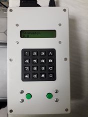
Function B (Stopwatch):
This mode turns on the enlarger at the press of the start button, simultaneously counting the time elapsed with an acoustic
signal every second. A subsequent press of the button stops counting and turns off the enlarger and halts the count. Pressing the button
again restarts operation. The time count is reset by simultaneously pressing the * and # keys on the keypad. You
can not enter time with the keypad in this mode.

Function C (Countdown):
This mode allows one to enter a time via the numeric keypad (simultaneously pressing the * and # keys on the keypad performs a reset). Pressing the start button turns on the enlarger and simultaneously counts down starting from the time set with an acoustic signal every second. A new press of the button turns off the enlarger and pauses the timer. Pressing the button again restarts operation. When the time reaches 0 the enlarger turns off and the timer is reset to the time initially chosen.

Function D (Countdown with initial enlarger focus)
This function is identical to the C function, but the first press of the button turns on the enlarger but does not start the counting of
the time. A subsequent press of the button turns off the enlarger. The third press turns on the enlarger and also begins the
countdown as for function C. The function is used to perform manual masking or burns that require precision placement. Ex: Set a time of 5 seconds for a burn, put the red filter in place, push the button, position the cardboard / hands / etc under the beam of light, push the button and the enlarger is turned off. Push again to finish the exposure.


F-stop mode

In this mode there are 4 additional functions, selectable with the keypad using the keys (A, B, C, D):

Function A (F/stop precision setting):
This mode runs the timer as a simple switch. The button is pressed and the enlarger turns on. A subsequent press and the
enlarger is turned off. The function can be used to focus or for the positioning of the easel/paper. This mode also selects the precision of f-stop units. Pressing the keys from 1 to 0 on the numeric keypad will select the precision that will be used in the functions B, C, and D in f-stop mode. The selectable accuracies are 1; 1/2; 1/3; 1/4; 1/6; 1/8; 1/12; 1/24; 1/32; 1/48 stops. This value is saved to EEPROM and restored after a power cycle or reset. The value is also displayed on the second line of the LCD while in the f/stop modes.

Function B (Test Strip):
This mode allows making a test strip with increasing exposure steps in f-stop units (precision is chosen in function A). The base exposure is chosen through the keypad in seconds. The enlarger is started with the start button with the paper completely uncovered. After the base exposure and at each f/stop interval thereafter, there will be an acoustic signal of three short beeps and one long to indicate to cover a portion of the paper (test strip) with a piece of cardboard. One continues in this way until the coverage of the paper is complete. By pressing the start button, the enlarger is shut off and the timer stops counting. One can reset the time with the simultaneous pressing of the * and # keys of the keypad.

Function C (Countdown with + or - exposure adjustment in f/stop units):
This mode allows one to enter a time via the numeric keypad (simultaneously pressing the * and # keys on the keypad performs a clear). The * key decreases the time by a stop or fraction thereof according to the set precision in function A. The # increases the time in a similar fashion. Pressing the start button then turns on the enlarger and begins the countdown, starting from the time set, with an acoustic signal every second. Another button press turns off the enlarger and pauses the timer. Pressing the button again restarts
operation. When the time reaches zero, the enlarger is turned off and the timer is reset to the time initially chosen. This function can be used to make test strips with modified f-stop exposures on the same paper; A different portion of a test print is uncovered and a complete exposure made with the desired increased or decreased time from the base exposure.

Function D (Masking / burn f-stop):
This mode allows entering a time via the numeric keypad (simultaneously pressing the * and # keys on the keypad performs a clear). Once the time set, # sets the timer to carry out a burn, while * a mask, at the current f/stop precision setting.

Burn: Pressing the # key is increments the set time by one stop (or fraction thereof according to the set precision in function
A). Then, pressing the start button turns on the enlarger and begins part of the countdown. During this time only the part of the image to burn is exposed. At the end of the burn time the timer stops by switching off the enlarger, and then displays the time associated with the exposure of the entire image. Pressing the button turns on the enlarger and the countdown resumes to the end of the base time.

Mask: Starting from an entered base time, pressing the * key calculates the masking time according to the set precision in function A. Then, pressing the start button turns on the enlarger and at the same time the first part of the countdown. During this time the area of the image to be masked is covered. At the end of the mask time, the timer time stops by switching off the enlarger, and showing the remaining time for the entire image. The mask is removed and the button pressed again. The enlarger is switched on and the countdown of the balance of the base time completes and the enlarger is shut off.
 
OP
OP

DonF

Member
Joined
Jul 19, 2016
Messages
285
Location
Saint Charles, Il
Format
Large Format
To give proper credit, my code is based on the work done here:

https://github.com/ciromattia/timerino
and
https://www.analogica.it/upgrade-timer-con-keypad-t6797.html

The first link is a very old version without the multi-channel feature.

The second is from the analogica.it Italian web site. It was produced as a finished sold unit with LED displays, but retained the LCD capability in the code by defining a different model type. The author had sort of ignored updates for the LCD model, so I fixed the formatting issues and added in conditional compilation statements so the code would work with either version.

There were a few other cut and paste bugs affecting the time variables. I added back in saving the sound and mode settings to EEPROM. I also fixed a rounding error in the f/stop increment/decrement function that helps gives a more consistent result if stepping up or down, then back to original value.

Don
 
Last edited:
Joined
Jul 31, 2012
Messages
3,362
Format
35mm RF
I've seen a few of these made over the years, but the original Nocon always made the most sense to me, but he invented it of course.

You've done a great job with this one. I could totally see myself using it. Just needs a foot pedal!
 

MattKing

Moderator
Moderator
Joined
Apr 24, 2005
Messages
53,262
Location
Delta, BC Canada
Format
Medium Format
OP
OP

DonF

Member
Joined
Jul 19, 2016
Messages
285
Location
Saint Charles, Il
Format
Large Format
Thank-you, gentlemen. In fact, I wired a jack for foot pedal in parallel with the red button.

Best regards,

Don
 

awty

Subscriber
Joined
Jul 24, 2016
Messages
3,659
Location
Australia
Format
Multi Format
Excellent work Don.
Thanks for taking the time to put up the build details.
Might try sometime, looks a lot easier than using an old analog timer and a f stop chart and a lot of mental arithmetic.
The electronics look pretty straight forward (with out looking too deeply at it), its the programing that I will have trouble with.
 

RalphLambrecht

Subscriber
Joined
Sep 19, 2003
Messages
14,661
Location
K,Germany
Format
Medium Format
I've seen a few of these made over the years, but the original Nocon always made the most sense to me, but he invented it of course.

You've done a great job with this one. I could totally see myself using it. Just needs a foot pedal!
I find foot pedals more of hindrance;usually stepping on it accidentally!
 
OP
OP

DonF

Member
Joined
Jul 19, 2016
Messages
285
Location
Saint Charles, Il
Format
Large Format
Here are updated software files for the timer, I added display of the channel number to the Setup mode. I also corrected the f/stop time calculation for the Teststrip function to apply proper rounding rather than truncating the floating point calculation, resulting in slightly better accuracy. I had already applied the same fix to the other f/stop functions.

I am including the Arduino sketch and keypad library in the zip file. I am also including the Intel hex file for burning the software to an ATmega 328p chip. The additional text file shows the high and low fuse bits for the chip, which are set in the software used to program the chip.

Finally, I'm including a higher resolution "Fritzing" diagram of the Arduino connections for the timer.

Regards,

Don

Schema_CMG001A_bb_web2.jpg
 

Attachments

  • Timerino_multich.zip.txt
    7.9 KB · Views: 442
  • Timerino_multich.ino.hex.txt
    42.4 KB · Views: 312
  • ATMega_328P_Fuses.txt
    67 bytes · Views: 333
OP
OP

DonF

Member
Joined
Jul 19, 2016
Messages
285
Location
Saint Charles, Il
Format
Large Format
Wiring diagram for ATmega328p chip version - Use .hex code and fuse settings above to program chip with your programmer.

Don
Schema_CMG001A_bb_Chip_web.jpg
 
OP
OP

DonF

Member
Joined
Jul 19, 2016
Messages
285
Location
Saint Charles, Il
Format
Large Format
If you try to build the timer with th standard keypad Aeduino library, the keypad input won't work quite write. Three entries for each key pressed will be registered

To fix, use the attached version of the keypad library. Remove the ".txt" portion of the file name, unpack and install normally.

Don
 

Attachments

  • Keypad.zip.txt
    17.8 KB · Views: 385
Joined
Aug 24, 2018
Messages
3
Location
Northern Ireland
Format
35mm
Great work Don, I tried the Italian version of the code but couldn't get the display to work correctly. Your version worked first time. I might try running it on an arduino nano. I'll post a picture when it's boxed up :smile:
 
OP
OP

DonF

Member
Joined
Jul 19, 2016
Messages
285
Location
Saint Charles, Il
Format
Large Format
Great work Don, I tried the Italian version of the code but couldn't get the display to work correctly. Your version worked first time. I might try running it on an arduino nano. I'll post a picture when it's boxed up :smile:
Great, I'd love to see it. One improvement I made was to put a "snubber" resistor and cap across the high-voltage relay contacts. That prevented the Atmega from resetting occasionally when the stabilized power supply for my enlarger (inductive load) switched on and off. I can post details, if needed.

I'd enjoy seeing the packaging. Glad you picked up the special "keypad" library. The current one does not work correctly.

Best,

Don
 
Joined
Aug 24, 2018
Messages
3
Location
Northern Ireland
Format
35mm
Great, I'd love to see it.

Well Don, I got side tracked by a million other jobs but I got there in the end. I have the timer working and boxed up. Hope you like the photos.
I designed the pcb and got it made in China (10 of them for $11 delivered). I decided to use a transformer with two 9V secondary's, that way I could provide a separate supply for the relay board and the arduino circuit keeping them totally isolated. The components on the board are just rectifiers, voltage regs and smoothing capacitors for the two supplies.

I bought a red lcd for the display but unfortunately it didn't seem to work, so just a regular one in for now until I get another.
I didn't want to chop plugs off my Durst enlarger so fitted a euro style 2 pin socket on the back of the box, that way my enlarger cables stay original.

Ralph
 

Attachments

  • 20190101_150144.jpg
    20190101_150144.jpg
    910 KB · Views: 731
  • 20190101_150257.jpg
    20190101_150257.jpg
    816.5 KB · Views: 562
  • 20190101_150926.jpg
    20190101_150926.jpg
    645.2 KB · Views: 619
  • 20190101_150949.jpg
    20190101_150949.jpg
    630.6 KB · Views: 586
Photrio.com contains affiliate links to products. We may receive a commission for purchases made through these links.
To read our full affiliate disclosure statement please click Here.

PHOTRIO PARTNERS EQUALLY FUNDING OUR COMMUNITY:


Ilford ADOX Freestyle Photographic Stearman Press Weldon Color Lab Blue Moon Camera & Machine
Top Bottom