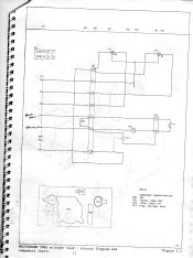
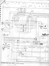
idon't have the diagram for the 500c controler. they where sent to me by someone else. i will ask if they have it. they where worried about posting the diagrams due to copywrite issues, i emaild simon at ilford for premission but haven't heard back yet but still posted it hope they don't mind.
Hi Mitch,
While I respect peoples worries about copyright issues, I also think this is getting a bit out of hand. We are talking about decades old equipment, that has gone out of production a long time ago. In addition, Ilford posted scanned documentation themselves freely available on their website.
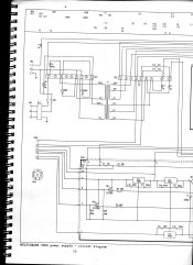
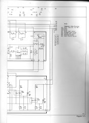
Lastly, I contacted Ilford directly about this very same issue of the older type MG500 units circuit diagrams and component layouts through the response link on their website. They were friendly enough to answer that they didn't have it available, but would add it if they ever dug up anything from their archives.
Frankly, I think Ilford will, and should, not mind. Anything that helps old equipment - and our hobbies / work! - going, by allowing repairs, is beneficial to Ilford, not detrimental.
so are you guys saying just change the wire pin places and it should work?
thanks
mitch
Yes and No (oh isn't real life beautiful

).
Yes if they need to be switched,
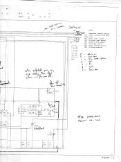
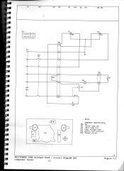
no if you only need to replace the connector / plug but not change wire layout. This latter option was justly raised by Steve, with his question about the front/back layout of the plug, and whether or not Ilford mixed up the diagrams.
To determine if "No" is the case, I say "measure the voltages" on the plug in the power supply, so as to determine what is right and what is wrong... Get a multimeter.
Actually, since Ilford did change the plug by adding the pin, it still
is likely they changed the wiring. Don't ask me why actually, since it seems no real significant change to the enlarger head was made requiring rewiring. The only reason I can think of than is that the changed layout allowed for easier wiring
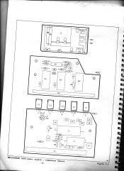
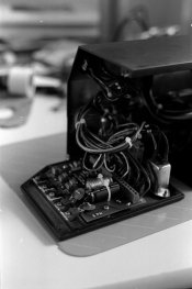
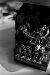
inside the 500S power supply and thus easier assembly / manufacture of the units. If you look at the photos of my unit that I posted, you can actually see that the wiring is quite complex inside, with thick bundled sets of individual wires. Maybe it was just a convenience / manufacture issue?
But maybe someone else with more electronics knowledge can give a more informed comment about the re-wiring.