Fujimoto CP31 (Print processor) - transformer burned out

Touch

D
Touch

  • 0
  • 0
  • 18
Pride 2025

A
Pride 2025

  • 1
  • 0
  • 59
Tybee Island

D
Tybee Island

  • 0
  • 0
  • 60
LIBERATION

A
LIBERATION

  • 5
  • 3
  • 124

Recent Classifieds

Forum statistics

Threads
198,348
Messages
2,773,352
Members
99,598
Latest member
mcafeejohn
Recent bookmarks
0

Cophoto

Member
Joined
Jul 27, 2024
Messages
1
Location
Hamburg
Format
Medium Format
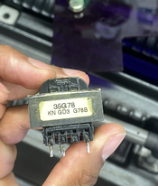
Hello everyone, unfortunately I made the stupid mistake and connected the device directly to the socket without stepdown, so the processor got 230V instead of 120V. Everything went well for 20 seconds and then there was a loud bang and it smelled like something was burning. After an electronics technician examined it, it turned out that the transformer was gone and was visibly scorched. Unfortunately, this transformer can no longer be found under the model number.
Can someone show me an alternative?

Alternatively, is it perhaps possible to install a transformer that can handle 230V directly?


** service manual: https://www.silveruser.ca/Manuals/CP31 Service.pdf
 

Attachments

  • IMG_4015.jpeg
    IMG_4015.jpeg
    1.3 MB · Views: 61
  • IMG_4014.jpeg
    IMG_4014.jpeg
    1.3 MB · Views: 58
  • IMG_4013.jpeg
    IMG_4013.jpeg
    1.3 MB · Views: 51
  • IMG_4011.jpeg
    IMG_4011.jpeg
    184.9 KB · Views: 57

cmacd123

Subscriber
Joined
May 24, 2007
Messages
4,310
Location
Stittsville, Ontario
Format
35mm
you may be into engineering work. first you have to figure out if twice the voltage fried anything else.
second if the rest of the unit is repairable find a transformer with the right output voltage, big enough curent output (YES the engineering part) with the primary for your local power system. (we call that Hydro here, but in some places it is the "Mains") then ofcourse you will proably have to work up a mounting.
 

Rudeofus

Member
Joined
Aug 13, 2009
Messages
5,070
Location
EU
Format
Medium Format
It looks like the board itself is fine. The rectifiers, the electrolytic capacitors both look good, and the voltage regulators (these three legged ICs which look like big transistors) also look good in that pic. You may be lucky and it was really the transformer which took the fall for the rest.

There are companies, which will make you a new transformer to spec. For this you need to find out the label on these two voltage regulators. These labels will tell you their input voltage, and from that we can determine the AC output voltage of your transformers. You'll also have the get the exact dimensions of the transformer core, there's a very high chance it's a standard size which is available at outfits which make transformers.

If a new transformer is all you need, expect to pay 10-30€ for a new one, if the exact voltage and power rating is a stock item somewhere. If you need a custom transformer wound to spec, then expect to pay 50-100€.
 

koraks

Moderator
Moderator
Joined
Nov 29, 2018
Messages
22,131
Location
Europe
Format
Multi Format
is it perhaps possible to install a transformer that can handle 230V directly?

Yes.

What's the text on both voltage regulators, the ones between the big blue capacitors?

The easiest solution is probably to get a generic AC-DC switch-mode power supply that outputs either the required voltage(s) directly, or one of both voltages you need, or something slightly higher (3V+ or so) than the highest voltage you need. Then make any other voltages you need with buck converter modules. There's a couple of ways you can do this; either you can make DC voltages that you feed into the existing rectifiers, regulators etc. Or alternatively you could bypass the existing rectifiers, filter caps and regulators and feed your self-made DC voltages directly into the output of the regulators.

It's possible that one of the voltages is a positive one and the other a negative and that the regulators are e.g. a 780x (positive0 and a 790x (negative); don't worry if this is the case since you can also use a buck converter to make a negative voltage. I suspect this dual pos/neg supply is what you've got given the placement of the first pair of buffer caps and the one regulator with the heatsink while the other doens't have one.

Yes, you could also try to find a suitable transformer; it may or may not be difficult to find. These days a LF transformer like this one is generally a little harder to find and a little more expensive than a similarly rated SMPS due to the cost of copper.

The main challenge with all this is to make your new solution fit into the original space. With a bit of luck you have some room to play with. If you want to make things really hard on yourself, look for a virtually identical transformer that will fit in the existing PCB holes. If you just want to get this show on the road, I'd very firmly recommend to drop that plan and go for a mechanically more flexible approach.

The advantage of using an SMPS is that they'll generally accept a wide range of input voltages; e.g. 100-240V, while maintaining the same output. With an old-fashioned transformer this isn't possible.
 

bernard_L

Member
Joined
Feb 17, 2008
Messages
2,003
Format
Multi Format
You can have a service manual (presumably with schematics and parts list) there:
With this you will know at least the voltage rating of the original transformer. As to the current rating, if it's not documented, I'd say make sure the new transformer is at least as big as the original one (which is actually rather small). Transformer power goes more or less like size.

Another way would be to find out the model of the voltage regulators. They seem to be mounted such that one is hidden... If they are fixed-voltage, find out the min input voltage from the datasheet (output + dropout), add a couple volts as margin, and take that as the RMS AC output required from the transformer. (yes, peak is 1.4x larger but rectified equals peak only with zero current draw). Also check the voltage rating of the first two capacitors (between the transformer and the regulators).

If I were in your shoes, to save the processor, I'd not hesitate, if space is the problem, to mount a transformer in a separate insulated box, with proper mains receptacle, fuse, and on/off switch. And run low-voltage AC from the transformer secondary(-ies) to where on the PCB they were originally. Or, once decided to have an outboard extension, buy two "bricks" of the proper voltage. Either direct connection to the output of the regulators (remove them) or higher but acceptable (to the regulators and capacitors) voltage to the input of the regulators. Observe proper polarity.

What I wrote above assumes you have some basic knowledge of electrical circuits, or can rely on some local in-person assistance.
 
Last edited:

koraks

Moderator
Moderator
Joined
Nov 29, 2018
Messages
22,131
Location
Europe
Format
Multi Format
They seem to be mounted such that one is hidden.

The front one can be bent downward revealing the markings in the back one. So this isn't a major issue.
They're fixed voltage given the lack of passive components around them apart from the buffer caps. Most likely 780x. Current will be low since there's little in the way of a heatsink; likely any transformer with an output of 1A will be ample.

As said I'd forego the regular transformer given today's marketplace.
 

bernard_L

Member
Joined
Feb 17, 2008
Messages
2,003
Format
Multi Format
Just notice the OP had provided a link to an open-access service manual.
  • For the control board, no schematics, just a parts placement diagram. Not very helpful.
  • DC voltages are listed as +8V, -8V. Most probably 7808 / 7908 regulators. Datasheet specifies 11v min input, up to 17V nominal (35V absolute max). I would chose a transformer with 12V AC secondary. Or a (pair of) switched mode power supplies (DC bricks) 12v each.
  • There is a lot of stuff running off 100V AC. Pumps, transport motor, heaters.
    • you still need to provide 100/110V AC via a mains step-down transformer
    • maybe some of the said components were also damaged when you supplied 220V AC.
 

Rudeofus

Member
Joined
Aug 13, 2009
Messages
5,070
Location
EU
Format
Medium Format
Just notice the OP had provided a link to an open-access service manual.
  • For the control board, no schematics, just a parts placement diagram. Not very helpful.
  • DC voltages are listed as +8V, -8V. Most probably 7808 / 7908 regulators. Datasheet specifies 11v min input, up to 17V nominal (35V absolute max). I would chose a transformer with 12V AC secondary. Or a (pair of) switched mode power supplies (DC bricks) 12v each.
  • There is a lot of stuff running off 100V AC. Pumps, transport motor, heaters.
    • you still need to provide 100/110V AC via a mains step-down transformer
    • maybe some of the said components were also damaged when you supplied 220V AC.

Good point with the manual, however: if you need 11-12V DC input voltage for these regulators, then you should rather choose a 2x9V output transformer, since a bridge rectifier plus capacitor will turn this into 9V*sqrt(2)-1.4V = 11.3V, which is all you need. Providing the rectifiers with 12V AC will just burn more power, which means the bare, uncooled voltage regulators may become very hot.

If the OP already replaces the transformer, OP may buy a transformer with 230V primary voltage right away and convert his box to European standards. There's absolutely no point in using a transformer wound for 110V and then using an extra step down transformer.
 

bernard_L

Member
Joined
Feb 17, 2008
Messages
2,003
Format
Multi Format
Good point with the manual, however: if you need 11-12V DC input voltage for these regulators, then you should rather choose a 2x9V output transformer, since a bridge rectifier plus capacitor will turn this into 9V*sqrt(2)-1.4V = 11.3V, which is all you need. Providing the rectifiers with 12V AC will just burn more power, which means the bare, uncooled voltage regulators may become very hot.
I had already addressed this point in my previous post:
(yes, peak is 1.4x larger but rectified equals peak only with zero current draw)
And, with a bridge rectifier, one also loses two diode forward voltages (silicon junction? schottky?)
Which is why selecting Veff equal to the desired rectified Vdc is a working approximation.
Rectified-voltage-waveform-by-FBR-circuit-with-ripples.png

(credit: https://www.researchgate.net/profil...tage-waveform-by-FBR-circuit-with-ripples.png)

If the OP already replaces the transformer, OP may buy a transformer with 230V primary voltage right away and convert his box to European standards. There's absolutely no point in using a transformer wound for 110V and then using an extra step down transformer.
Sure, whatever transformer (mains ->12V) is easiest to procure.
Read the end of my post. The point is that pumps, transport, heater, will still require 100V. If they are still alive. It was that step down transformer I was referring to.
 

koraks

Moderator
Moderator
Joined
Nov 29, 2018
Messages
22,131
Location
Europe
Format
Multi Format
loses two diode forward voltages (silicon junction?

Virtually guaranteed to be Si, yes. Those bridge rectifiers as in the photograph are nearly always plain silicon diodes comparable to 1n400x.

Which is why selecting Veff equal to the desired rectified Vdc is a working approximation.

Yes, and that'll work just fine. Using a 9VAC transformer will leave a 7809 starving, which means it may/will lose regulation.

11.3V, which is all you need.

No no. 780x regulators (99.9% certain that's what's used here) need something like 2.5V headroom. Double diode drop is another 1.4V, so you need let's say 4V above target Vdc. That's 13V, which means a little over 9VAC. Using a nominal 9VAC transformer may or may not work, depending on its specifics, operating conditions, effective line voltage at the wall etc. All considered it's an unnecessary risk, although it will likely 'work'.
 

Rudeofus

Member
Joined
Aug 13, 2009
Messages
5,070
Location
EU
Format
Medium Format
As you all know, a 230-->9V transformer outputs 9V when driven to its rated current, something nobody in his/her right mind would ever do. Output voltage will be substantially higher at lower current draw, especially for these small transformers.

Therefore your 9V transformer will provide you with all the head room you ever wanted.
 

オオヤ

Member
Joined
Dec 7, 2024
Messages
4
Location
japan
Format
4x5 Format
Hello.

I had the opportunity to maintain a CP31 that had a similar problem, so I'll share it.
PXL_20241129_140743899.MP~2.jpg
In my case I had other CP31s that worked fine so I chose the transfomer based on that.

The specs are as follows:
Input Voltage: 100V
Output Voltage: 15V-0V-15V
Output Current: 50mA (…,probably)

So I chose a Toyozumi HP-155 transformer and attempted to repair it.
https://www.toyozumi.co.jp/products/hp.html )


Please refer to the attached note for wiring.
1000015350.jpg

I believe that terminal 3 on the original transformer is probably for fixing to the circuit board and is not electrically connected.

I was able to fix it this way. It looks like a chimera now... .
PXL_20241206_045254779.MP~2.jpg

PXL_20241206_055520552.MP~2.jpg


The CP31 is a valuable color processor, so let's all repair it and enjoy silver halide photography forever.

1000015358.jpg
 

オオヤ

Member
Joined
Dec 7, 2024
Messages
4
Location
japan
Format
4x5 Format
That sounds unusually low for this size and type of transformer. It's probably 500mA.

I'm not sure about this point either.
However, when I consulted a transformer specialty store, I was told that the electrical capacity of a transformer is determined by its physical size, and that the original transformer had an electrical capacity of 0.8VA.

The transformer with a capacity of 0.8VA is the Toyozumi HP-153, but I chose the HP-155 to be on the safe side.
As a result, the HP-155's shape is a bit larger than the original Transformer.

I think it's probably a circuit that controls the on/off of motors and heaters, so it doesn't require that much current.

Please use this as a reference.
 

オオヤ

Member
Joined
Dec 7, 2024
Messages
4
Location
japan
Format
4x5 Format
That would be nice, although I think the horizon is much more finite. Given that you're in Japan, I assume: what kind of papers do you use? The offering you have in Japan is different from ours; do you use Fuji Everbeauty paper?
In Japan, Fuji Color Professional Paper is the most popular.
( https://www.yodobashi.com/product/100000001001256218/ )

Some people also cut up minilab roll paper and use it, but they are in the minority.
http://www.s-souko.com/item/pg179.html )
 

koraks

Moderator
Moderator
Joined
Nov 29, 2018
Messages
22,131
Location
Europe
Format
Multi Format
Ah thanks, yes, I keep forgetting about the "Pro-G" paper. It's interesting that Fujifilm in Japan apparently still offer boxes of cut sheet paper. Here in Europe, cut sheet is only available from 3rd parties. Personally I use rolls.
 

オオヤ

Member
Joined
Dec 7, 2024
Messages
4
Location
japan
Format
4x5 Format
Oh, really !?
I never imagined that Europe would have such an environment.

We Japanese were envious of the cheapness and variety of film available in Europe and the United States.
It's difficult because the Japanese Yen is so cheap, but I sometimes import from Photo Impex or B&H.
(Kodak products are too expensive in Japan!)

By the way, are there any other popular personal color processors in Europe and the US besides Fujimoto?
In Japan, the only other option is the Jobo Tank, and the price of used Fujimoto CP-series has skyrocketed in recent years.
 

koraks

Moderator
Moderator
Joined
Nov 29, 2018
Messages
22,131
Location
Europe
Format
Multi Format
Oh, really !?
I never imagined that Europe would have such an environment.

This is because the Fujifilm paper sold over most of the world is made in Europe, and the manufacturer here does not offer cut sheet anymore. The market is too small to keep the confectioning operation going.


are there any other popular personal color processors in Europe and the US besides Fujimoto

Here in Europe, Fujimoto processors are virtually nonexistent. The main manufacturer of tabletop processors is/was Thermaphot, which also made the Durst RCP processors. Those are what you mostly see here. Bigger machines (50cm and bigger) are often made by Colenta. There are a few others as well, but these are the most common brands at least as far as I can tell.
 
Photrio.com contains affiliate links to products. We may receive a commission for purchases made through these links.
To read our full affiliate disclosure statement please click Here.

PHOTRIO PARTNERS EQUALLY FUNDING OUR COMMUNITY:


Ilford ADOX Freestyle Photographic Stearman Press Weldon Color Lab Blue Moon Camera & Machine
Top Bottom