DIY LED horizontal 8x10 enlarger

The Padstow Busker

A
The Padstow Busker

  • 0
  • 0
  • 20
End Table

A
End Table

  • 1
  • 1
  • 102
Cafe Art

A
Cafe Art

  • 8
  • 6
  • 216
Sciuridae

A
Sciuridae

  • 6
  • 3
  • 201

Recent Classifieds

Forum statistics

Threads
197,663
Messages
2,762,688
Members
99,436
Latest member
AtlantaArtist
Recent bookmarks
0

Fraunhofer

Member
Joined
Jan 1, 2016
Messages
208
Location
East coast
Format
Multi Format
This has been my quarantine project: building a horizontal 8x10 enlarger with a LED light source.

I have been (or still am?) on a steady quest for larger format negatives mostly for Pd/Pt printing. So last Christmas I got an Intrepid 8x10. Once I had some nice 8x10 negatives, I felt an urge to make large silver prints. It is also was clear that a vertical 8x10 enlarger would not fit into my darkroom space.

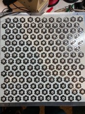
LED light source: Approximately 150 3W LEDs on a 12x12 aluminum heatsink
IMG_2367.jpg
40 red, 50 blue and 60 green LEDs. They're stuck to the heat sink using double sided heat conducting tape. They are driven by Meanwell LDD-H 700mA drivers (12 altogether) and wired such that the central area can be controlled separately from the outside area. The drivers are PWM controlled by an Arduino Mega, which also conveniently serves as timer. I added a NTC thermometer in the center of the heatsink, so that it can switch itself off if gets to 60C, which given the thermal resistance of the LED base should correspond to a temperature of 110C at the junction. The fully assembled light source can run for ca. 15 minutes at full steam before it reaches that point.

For diffusion I use two layers of rosco diffuser 6 inches from the LEDs, which gives a very uniform light distribution of better than 1/3 of a stop corner to corner of 12x12 square inches. Also the inside of the LED box is coated with aluminum foil for reflection, to avoid light fall-off at the edges. The blue LEDs are not quite blue enough and so I get grades from 00-4. Printing times are quite uniform across the paper grades so 50/60 blue/green LEDs works.

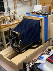
The enlarger body is made of 3/4 inch birch plywood and my first major table saw project. I use my Intrepid 8x10 for the front standard, bellows and focusing; but the body is built such that I can replace those with custom parts later on.
IMG_2502.jpg

The lower left shows nicely the focusing rail for a later upgrade. The whole contraption sits on my main table and projects onto an easel (4x4 plywood) screwed to a sturdy storage shelf. With a 300m lens I need 60 inches distance to achieve a 4-fold enlargement to 32x40. At that size I have about 1/2 stop light fall-off in the corner, which I hope to reduce by tuning down the center section of the light source.

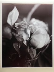
I managed to get my first 16x20 print done yesterday (still a 4-fold enlargement, I cropped
the image). Printing time is 40s at f32.
IMG_2523.jpg

My 42 inch wide roll of paper is supposed to arrive sometime next week, dealing with those print will be its own set of challenges. In any case, so far so good. Loads of fun and challenges.
 

seall

Member
Joined
Jan 26, 2013
Messages
45
Format
Multi Format
This is very interesting, hope you don't mind me asking a few questions as I am building something similar using less LDD's and less LED's. I have found the LDD's to be very stable.

What LED's did you use, and when you exposed at f32 for 40s were you using the LED's at their most efficient level or was it a higher level?

When testing heat dissipation is your heat loss quick enough for a continuous workflow?

As it all heats up have you found any difference in light output with the varying heat levels?

How are you getting your pwm, as in how are you making it? I2C 12bit, direct manipulation of registers, some other way?
 
OP
OP

Fraunhofer

Member
Joined
Jan 1, 2016
Messages
208
Location
East coast
Format
Multi Format
@seall The LEDs are no-name from ebay, 3W they come mounted on little aluminum stars. They are rated for 700mA forward current and this is what I am running them at. If you look at the voltage drop, it's clear they are not truly 3W but more like 2-2.5W. To get the print at f32/40s I ran the green LEDs at 75% and the blue ones at 25% and the red ones not at all. I get all paper grades by running blue and green so that they add up to 100%. I use red to either get a safelight to positon paper etc. or to obtain white light for focusing.

As I said with all LEDs at full power I have about 10-15 minutes before the heatsink gets to 60C and then I switch off (or the arduino does). With green and blue like above, I get about 20-25 minutes. I believe, based on some tough calculation, that with forced air cooling you could get into an acceptable continuum mode.

The light output appears stable, though I have not measured it as function of temperature. My understanding of LEDs leads me to believe that if you drive them at constant current, as I do, their light output should be quite stable and rather independent of temperature. If OTH you drive them with constant voltage, then they will show quite significant changes in light outpup.

The PWM comes from an Arduino Mega and it has built-in timers which create a PWM output without further ado.
 

seall

Member
Joined
Jan 26, 2013
Messages
45
Format
Multi Format
Fraunhofer,

My system takes roughly twice the time to cool as it does to heat up (with no extra cooling). My LED's are on a 6mm plate and I have drilled holes between them for forced air using pwm controlled noctua fans , when tested with cooling on after exposure I have managed to drop the cooling time to equal the heating time. I am some DS18B20's set into the aluminum plate to set a "cooling flag" to on/off which allows the fans to go on (if required) when the lights are not in use. Noctua fans are quiet and with pwm can be made to stop very quickly.

Have you had a mess about with the PCA9685? I wanted to be able to program my light levels for multi-step split grade exposures rather than set by pot and have found the PCA9685 suits my own setup better for the lower light levels, although I have stuck with the chips timer/register settings for the fans as they don't require such granular control.

Like your setup though, hope you get many years enjoyment from it as it sounds as though you have it working quite well.
 

koraks

Moderator
Moderator
Joined
Nov 29, 2018
Messages
20,996
Location
Europe
Format
Multi Format
Have you had a mess about with the PCA9685? I wanted to be able to program my light levels for multi-step split grade exposures rather than set by pot and have found the PCA9685 suits my own setup better for the lower light levels
Just my two cents, but for a B&W split grade approach, I don't think you need the 12-bit resolution of the PCA9685. The 8-bit native PWM performance of an Arduino/Atmel uc should be perfectly adequate.
For color work (RA4 paper), it's a different story. For that purpose, you really need the additional resolution to reach proper linearization and sufficiently small 'filter' changes.
 

seall

Member
Joined
Jan 26, 2013
Messages
45
Format
Multi Format
Just my two cents, but for a B&W split grade approach, I don't think you need the 12-bit resolution of the PCA9685. The 8-bit native PWM performance of an Arduino/Atmel uc should be perfectly adequate.
For color work (RA4 paper), it's a different story. For that purpose, you really need the additional resolution to reach proper linearization and sufficiently small 'filter' changes.

I am trying to get roughly the same grade placements and paper type compensation coefficients as the Zone VI system and am using a combination of 1A and 1.5A LED's with no filters, although I am not running them anywhere near full power. I found that 8-bit did not give me enough sensitivity at low light output for either set of LED's whereas 12-bit works a little easier when trying to set the full 14 steps in grade (0-0+ to 5+), some of which have to be more accurately placed than the others. Maybe it would be easier with a higher number of lower power LED's. This was not a problem for me when using potentiometers which give a hardware choice of linear vs logarithmic. Maybe I am doing something wrong or missing something which would not surprise me 1-bit..?
 
OP
OP

Fraunhofer

Member
Joined
Jan 1, 2016
Messages
208
Location
East coast
Format
Multi Format
I am using this thing for a week now, so this all may change down the road. But for now:

I figured that 8 bits would be fine, I mean there are 10 filters in a typical Ilford multigrade filter set, so that's 3.5 bit and 8 bit seems plenty. I guess it makes a difference, if one also use the PWM to set overall brightness: say you run at 1/8th power, then you loose 3 bits just to that and then it becomes tight to fit 10 grades.

In any case, my printing times are such that I won't have to reduce brightness and I have no plan to do color, ever (I am fairly red/green blind).

Regarding, forced air cooling, printing times with this system are in the same ball park as my Omega D5 (by design and I am happy that I nailed that). I never have had my enlarger light source on for 10 minutes or more, probably less than 5 minutes. With larger formats, wrangling the paper itself takes so much time that there is plenty of time between exposures, so I don't anticipate I will need cooling. Mechanically, there's room in the chassis to add fans, should the need arise.
 
Last edited:

Luckless

Member
Joined
Feb 9, 2016
Messages
1,362
Location
Canada
Format
Multi Format
What are you printing onto, and how is that going for the workflow?

Your project is looking great. I'm considering doing a similar rig for my 4x5 negatives. As much for the enjoyment of poking around with precision crafting as any other reason.
 
OP
OP

Fraunhofer

Member
Joined
Jan 1, 2016
Messages
208
Location
East coast
Format
Multi Format
What are you printing onto, and how is that going for the workflow?

Your project is looking great. I'm considering doing a similar rig for my 4x5 negatives. As much for the enjoyment of poking around with precision crafting as any other reason.

Thanks! Let me assure you there's very little precision crafting involved, when I build stuff.

I am printing onto Ilford Warmtone FB, which is my goto paper in smaller sizes as well. So far I have done 16x20, but I have a 42" wide roll coming this week. I will report how that goes. I should say that I also built a large rocking tray with a drain, so that I can do single tray processing. I do not have space for several trays in 32x40. I tested this in 16x20 and it works well, but needs some minor tweaks.
 

distributed

Member
Joined
Sep 11, 2020
Messages
127
Location
Switzerland
Format
Multi Format
This is a really nice project! The light source is a beauty and you did take good care of the heat issue. I also like the upgradeability to custom parts and the rail.

For diffusion I use two layers of rosco diffuser 6 inches from the LEDs, which gives a very uniform light distribution of better than 1/3 of a stop corner to corner of 12x12 square inches.

How are you measuring the light distribution, do you place a photometer where the photo paper would be?

The blue LEDs are not quite blue enough and so I get grades from 00-4. Printing times are quite uniform across the paper grades so 50/60 blue/green LEDs works.

Are you measuring your grade in ISO(R) range? I am currently refitting a Durst CLS 305 head with RGB LED illumination. The blue LEDs are quite standard in the 460-465 nm range, nothing royal blue or similar. In my first tests, I get an range of about 0.5-0.6 log Exposure on Ilford MGRC with blue illumination. ISO(R) 50 is what Ilford specifies for Grade 5, so I am pretty close. I also have to say that I measure my log Exposure as log(Exposure Time), so I am not taking lens flare etc. into account. With that being said, I assume if I am not able to reach what Ilford calls grade 5, then I am pretty darn close.

The drivers are PWM controlled by an Arduino Mega, which also conveniently serves as timer.

If PWM resolution poses a problem for you, you could also just run the G and B LEDs at full power for an amount of time related to the respective green and blue exposure. Thus, exposure precision is purely dependent on the exposure time control precision of your Arduino, which should be more than sufficient. This doesn't preclude dimming some parts of your light source if you find that this helps evenness of illumination. Or am I missing something?
 

koraks

Moderator
Moderator
Joined
Nov 29, 2018
Messages
20,996
Location
Europe
Format
Multi Format
If PWM resolution poses a problem for you, you could also just run the G and B LEDs at full power for an amount of time related to the respective green and blue exposure. Thus, exposure precision is purely dependent on the exposure time control precision of your Arduino, which should be more than sufficient. This doesn't preclude dimming some parts of your light source if you find that this helps evenness of illumination. Or am I missing something?
That will pose a problem when burning/dodging.
 

distributed

Member
Joined
Sep 11, 2020
Messages
127
Location
Switzerland
Format
Multi Format
I see. If you want to dodge or burn on a specific grade, then time-only control is out. I have gotten so used to dodging and burning with the hardest/softest grades that I sometimes forget about the other possibilities :smile:
 
OP
OP

Fraunhofer

Member
Joined
Jan 1, 2016
Messages
208
Location
East coast
Format
Multi Format
@distributed thanks for the nice words.

I measure the light distribution by exposing test strips with a Stouffer wedge, the wedge is 4x5 so easily can do one in the center and some in the corners. That is also how I determine paper grade: I expose grades 00-5 under my regular enlarger with the wedge and then compare what I get for different green/blue combinations. I used this to calibrate the grades on the new light source.

Heat turns out is a problem when turning on the focusing mode for prolonged periods of time, especially when aligning the whole system. I may add fan to solve that problem.

PWM resolution is currently not a problem, but somewhere in the thread a simple solution is mentioned: there are specific high-resolution pwm chips (they are really cheap).

Finally, I started printing 32x40. Since I am doing single tray a single print takes me about two hours (including toning and washing). Wrangling a roll of paper is rather different than sheets out of a box. But so far so good. I hope soon to have some results which I can show.
 

Cisco7

Member
Joined
Sep 14, 2020
Messages
3
Location
Miami
Format
35mm RF
Hi could anyone help me please with a BESELR 4x5 glass negative carrier. It does not completely and the light leaks ot
Thanks
 

MattKing

Moderator
Moderator
Joined
Apr 24, 2005
Messages
52,050
Location
Delta, BC Canada
Format
Medium Format
Hi could anyone help me please with a BESELR 4x5 glass negative carrier. It does not completely and the light leaks ot
Thanks
Welcome to Photrio.
As a new member here, you should consider posting both an introduction thread, and a separate thread setting out in detail the problem you are trying to solve.
The post in this thread is a bit fragmentary. But many here would be keen to help.
 

Cisco7

Member
Joined
Sep 14, 2020
Messages
3
Location
Miami
Format
35mm RF
Hi Matt Thank you for your welcome. Could you please show me how I may post an introduction and also how to ask our community for help. Pardon me for asking for help on your post.
Thanks Again
Francisco
 
Last edited:

MattKing

Moderator
Moderator
Joined
Apr 24, 2005
Messages
52,050
Location
Delta, BC Canada
Format
Medium Format
Sure.
For the introduction, go to the Introduce Yourself sub-forum index page, where you will see a list of thread titles. Click on the "Post New Thread" link at the top right.
Choose an appropriate thread title, and then introduce yourself in the body of the post.
Here is a link to the sub-forum: https://www.photrio.com/forum/forums/introduce-yourself-to-the-photrio-community.35/
You may want to read through a couple of examples to get a sense about how things go.
And as for the Beseler glass negative carrier, this thread is already in the Enlarging sub-forum, so that is probably as good a place to put your query as anything. Go up to the top of this page and click on the Enlarging header. That will get you to the Enlarging sub-forum index page, where you will see a list of thread titles. Again, click on the "Post New Thread" link at the top right. Choose an appropriate thread title - which includes the enlarger model you have, and then post your query.
If you have photos that illustrate the issue, they can be copied into the post.
 

andrewherrick

Member
Joined
Mar 26, 2009
Messages
4
Format
8x10 Format
Hi there, I'm interested in building a DIY 8x10 lightsource. I'm pretty good with tools and can solder, but don't have experience with arduinos. Could someone (Fraunhofer?) please help with a wiring diagram? Any guidance / instructions would be very much appreciated.

Kind regards

Andrew
 

koraks

Moderator
Moderator
Joined
Nov 29, 2018
Messages
20,996
Location
Europe
Format
Multi Format
Any guidance / instructions would be very much appreciated.

Gladly; I think @Fraunhofer hasn't visited this forum for a while, but others will be happy to help, me included.

I've done several LED enlarger light sources so far (for my own use); the latest version currently in use is reported on here: https://tinker.koraks.nl/photograph...gly-rgb-led-head-for-color-printing-revision/
Wiring diagrams etc. depend on many things; for the light source as such, it depends in particular on what LEDs (or LED modules) you'll use, how you'll drive them (current limiting, PWM) and what supply voltage you settle on. Then there's the controller part, which can range from fairly simple to very complicated.

Will you be doing B&W or also color printing?
 

andrewherrick

Member
Joined
Mar 26, 2009
Messages
4
Format
8x10 Format
Hi Koraks, thanks so much for your reply. I will only be printing B&W. I can either use a neutral coloured light source and multi-grade filters in front of the lens, or RGB LEDs and vary the colour balance to vary contrast. I think Fraunhofer did the latter.

I live in Australia so 240V AC from the wall. Not sure if your plans run AC or DC, if DC I have no preference, can buy whatever transformer is needed. I really have no clue about current limiting / PWMs etc. I think Fraunhofer bought LEDs off ebay, I think I have found ones that look right, they are 3W and star shaped like the ones he described.

Let me know if you are able to help with a wiring diagram, or PCB layout

Thanks again
 

andrewherrick

Member
Joined
Mar 26, 2009
Messages
4
Format
8x10 Format
I just had a look at your site... I see Branko asked for PCB layouts, and your preference was to not provide... that is fine. I see you linked to some driver boards on Ali Express... pre-made is fine, preferred even. I am proposing to make an 8x10 enlarger head myself, so fitting all this into an existing unit isn't a priority.

If you're able to assist with any guidance as to how to connect the drivers, what LEDs to get, what arduino I need (I really don't know anything about these...), what program I'd use... any assistance appreciated.

I'm ok with soldering but not looking to build from scratch if I can avoid it. If there are more expensive, pre-made components, that is fine.

thanks again!
 

koraks

Moderator
Moderator
Joined
Nov 29, 2018
Messages
20,996
Location
Europe
Format
Multi Format
The fact that you'll only do B&W helps to keep things simple!

I can either use a neutral coloured light source and multi-grade filters in front of the lens, or RGB LEDs and vary the colour balance to vary contrast.
Good; this gives you a simple option you could consider, as the former will be a little easier. Components would be something like this:
* 20-50W warm white COB LED for direct AC operation; something like this: https://www.aliexpress.com/item/1005007023067678.html
* Suitable COB LED heatsink, e.g. https://www.aliexpress.com/item/32754202850.html
* I'd recommend also getting a fan that mounts onto the heatsink; most of these are 12VDC so you'll need a small 12VDC wall wart power supply to power it from.
* You can use any regular enlarger timer and plug the LED into this.
In this setup there may be a very slight afterglow to your COB LED (but usually it's insignificant) which you'll just have to live with. If it's bothersome, try some other LEDs until you find one that doesn't exhibit this behavior (they're cheap anyway). The addressable RGB LEDs in the 'fancy' option above don't have this problem anyway.

This approach requires no microcontroller or coding; you just use a regular enlarger timer. You'll use Multigrade filters like with any bulb-based enlarger. You will still have to build a diffusion box so that the illumination of your negative is even. This challenge will be pretty much the same as with the fancy option I'll discuss below.


If you want to use "dial-a-grade" functionality where you basically have similar functionality to an Ilford 500 head, where you set the contrast grade and exposure time on a little screen by punching some buttons, you could build a more fancy version. You would need, for instance:
* Four or more 10W addressable 'smart pixel' LEDs. https://www.aliexpress.com/item/1005001379075638.html
* A suitable heatsink for each of the 10W LEDs. Something like this: https://www.aliexpress.com/item/1005003605697738.html
* A 12VDC power supply. If you use e.g. 4 LEDs, use e.g. a 5-6A rated unit. This can be something like this: https://www.aliexpress.com/item/4000594896227.html. if you use more LEDs, scale the power supply with it (!)
* A microcontroller of your choice; e.g. an Arduino UNO R4 WiFi https://store.arduino.cc/products/uno-r4-wifi
* A display and some form of data entry; for instance something like this: https://www.aliexpress.com/item/32475515474.html

There are roughly 80 million other ways and combinations of parts that will boil down to the same, so the above is just one possible approach. But it'll work and relies on fairly standard stuff for which plenty of code examples are available.

The display/keypad module I linked to should fit on top of an Arduino UNO-sized board, so that combination is convenient to use. You'll need to solder two wires to the display module for a GND and signal connection to the RGB LED modules. You power the UNO + display from the 12V of your power supply using the "Vin" pin. The LEDs are directly powered from the 12V power supply. All GND's need to be connected on your project.

You'll have to be creative in physically bolting everything together on your enlarger setup. You can use something like frosty/milky plexiglass as a diffusor. You may/will have to fashion some kind of diffusion chamber with the LEDs on one end and the diffusor at the other end, and a light-proof housing around it so you don't fog the paper, and this somehow needs to fit on/in your enlarger. The only advise I can give in this regard is "be creative"...

As to the number of LEDs you need: I expect you'll be able to do fine with 4 pcs of 10W RGB LEDs of the type suggested above. If you feel like beefing things up, you could use more. Keep in mind that your power supply needs to scale with the number of LEDs.

The real work will be in coding the system; you need to write the software for it, basically. If you have affinity with programming, this will be a huge bonus. If not, you'll either have to learn (which will take quite some time) or you'll have to bribe/convince someone else to do the work for you. To the best of my knowledge there's no ready-made software/code for this application that you can plug into your microcontroller of choice and it'll magically work. Even if I handed you the code that my enlarger runs on, it'd be useless to you; it's hardware-specific. On the plus side: it doesn't have to be very complicated to get the job done.

I'm always willing (to a reasonable extent) to give pointers and help with troubleshooting.


I see Branko asked for PCB layouts, and your preference was to not provide... that is fine.

Yeah, he did, and it's not because I'm trying to keep it a secret. The main consideration is that the approach is kind of idiosyncratic and especially for your case I would never recommend trying to recreate my system. There's plenty of far easier ways to get the job done (see above) and they will be perfectly adequate for B&W work. So I'm holding those designs back mostly because I don't want to send off people on some kind of crazy journey that'll just make them waste lots of time.
 
Photrio.com contains affiliate links to products. We may receive a commission for purchases made through these links.
To read our full affiliate disclosure statement please click Here.

PHOTRIO PARTNERS EQUALLY FUNDING OUR COMMUNITY:


Ilford ADOX Freestyle Photographic Stearman Press Weldon Color Lab Blue Moon Camera & Machine
Top Bottom