DIY Enlarger Timer Circuit?

Druidstone

A
Druidstone

  • 1
  • 0
  • 4
On The Mound.

A
On The Mound.

  • 0
  • 0
  • 11
Ancient Camphor

D
Ancient Camphor

  • 4
  • 1
  • 26
Flow

A
Flow

  • 5
  • 0
  • 29
Sciuridae III

Sciuridae III

  • 2
  • 0
  • 26

Forum statistics

Threads
197,794
Messages
2,764,484
Members
99,475
Latest member
ArabicaGlass
Recent bookmarks
0

olleorama

Member
Joined
May 10, 2009
Messages
525
Format
Multi Format
Good work kittyhawk. I want an outlet for a foot control to start the thing. Or for focus. Can that be incorporated?
 

kittyhawk88

Member
Joined
Sep 24, 2009
Messages
21
Location
Sydney, Aust
Format
Medium Format
Hi Olleorama,
a foot switch is really quite simple to incorporate. As I see it. The timer switching section has only 2 modes. Either safelight on and enlarger off or enlarger on safelight off. So the switching section just needs to have 2 way relay. I think a double pole double throw.. I need to think this one out. However a dual relay would be a better bet as someone somewhere will want to focus with the safelight on.

I'll add that to the requirements.

I will build the relays and terminal blocks into the enlarger but will leave the user to onnect it up. The eletrical regulations problem.. I don't have the moeny to get this pass regulatory requirements. So it's up to the user to wire those switches in country dependant etc. I'm working on a $39.00 USD target so that it's affordable. We want people to convert to f stop timing no discourage them.

I'll add the option into the website.
 

kittyhawk88

Member
Joined
Sep 24, 2009
Messages
21
Location
Sydney, Aust
Format
Medium Format
Updated Timer Interface

Worked out how to post pictures.

Here's the link if it does not work.
http://www.geocities.ws/fstoptimer/
I've started on the code design.
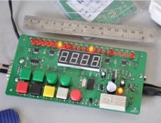
Have chosen to implement this design with PIC Microcontroller with an external quartz oscillator for accuracy to +- 0.001 seconds.
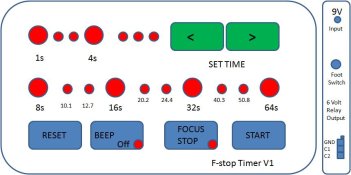
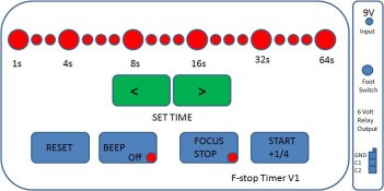
will implement a 6 volts switched relay output. you can use this to drive a relay.
C1 and C2 are toggled on and off . So you can switch the dark room lights on or off.
Focus lets you switch the enlarger on with no time limit
Reset lets you start all over again
Reset followed by > key lets you set time period
Reset followed by > key then left key lets you set test strip mode

Beep - sets beep off or on. When beep is off LEDs light to indicate time.
Beep on - needs no explanation

Start - starts the timer - Also slaved to footswitch.

Footswitch - will use a standard 3.5mm jack

9/12 volts input. Lets you use an external plug pack to power the unit instead of 4 AAs. Useful if using unit to drive external relays to power switch enlarger on or off and safelights on or off.

Comments please..
 

Attachments

  • f stop timer.jpg
    f stop timer.jpg
    42.3 KB · Views: 127

kittyhawk88

Member
Joined
Sep 24, 2009
Messages
21
Location
Sydney, Aust
Format
Medium Format
Would anybody object if we added say $5.00 USD to the completed meter purchase price to donated to the running of APUG?
Comments please , thanks.
 

George Nova Scotia

Subscriber
Joined
Mar 17, 2010
Messages
986
Location
Milford, Nova Scotia
Format
Multi Format
Very interesting project. I have more timers than I need at present but no f-stop timer, when you come up with the final cost I'll have to take a long look.

One suggestion, interchange the start and beep switches. Keeping the start away from the reset and placing it the corner may prevent accidents in the dark.
 

John Koehrer

Subscriber
Joined
Apr 3, 2004
Messages
8,275
Location
Aurora, Il
Format
Multi Format
I'd be interested at the $40-$50 mark depending on shipping to the US.
I'd also like to find something like this that would go from 1/30 sec to ~5 sec. in a similar price range. Kit form would be nice for me just for S&G.
 

ic-racer

Member
Joined
Feb 25, 2007
Messages
16,499
Location
USA
Format
Multi Format
I still have it somewhere. I will see if I can find it.


Steve.

I just checked to confirm it, but the box for the old timer pictured above has survived 35 years and has wound up housing the glow-driver on my R/C plane field box. In between housing a timer and the glow-driver it surprisingly housed my first home-made guitar distortion circuit, ca 1980.
 

kittyhawk88

Member
Joined
Sep 24, 2009
Messages
21
Location
Sydney, Aust
Format
Medium Format
F STop timer revised + progress updates..

Thanks Guys..

I've taken on board the suggestion to move the buttons..

There is s suggestion to simplify it to simply beep and light at every quarter stop.
What say you to that ?

Update:

Started work on the board layout . Using Protel.
BAsic program logic desing is nearly there.
Please bear with me while I work on this.

It's nearly X'mas and my boss wants me to tidy up so we can close up in time.

I am still shooting at 39+5 APUG donation.

I'll design 2 versions.
A Diyer version with all the board layout ready for relays and connectors.
This allows the 'kit ' folks to solder in the relays to switch your enlargers. you need to find your own box for this.

The safe retail version will be 6 v output to allow you to switch the enlarger externally.. using another box and relays.. another kit to be offered at some stage.

As for other time periods. I am implementing this timing using an external oscillator..

Given it is all software driven, The timer can be programmed to be any time period.

Hey maybe a built in USB port to allow you guys to flash the firmware..

This can become the universal timer , garden timer, enlarger timer etc. by just flashing the firmware..

I plan to get this done by Jan 2011...

Any beta testers out there.. PM me please.. thanks
 

Attachments

  • f stop timer.jpg
    f stop timer.jpg
    42.2 KB · Views: 125

kittyhawk88

Member
Joined
Sep 24, 2009
Messages
21
Location
Sydney, Aust
Format
Medium Format
f stop timer revised 1/4 stops key layout

Had a rethink and changed the key layout and LED layout. Simplifies the board layout a lot.

Normal mode - Will count up to selected time.
Test Strip mode - will count down.
 

Attachments

  • f stop timer v1.jpg
    f stop timer v1.jpg
    41.8 KB · Views: 152

jp498

Member
Joined
Oct 5, 2009
Messages
1,525
Location
Owls Head ME
Format
Multi Format
Count me in for a kit or two.

I'd bet we'd have a lot more relay choices if the relay voltage were 12 vdc. For instance, jameco does not have any 6v relays, but lots of 5,12,24v ones. I've been using about 40 omron 12v dpdt relays in my house to operate the lights for 10 years now and have only had one relay malfunction.

If there were room in the box for a relay & socket & power supply for the circuitry, that would be ideal too.
 

paul ron

Member
Joined
Jan 22, 2004
Messages
2,706
Location
NYC
Format
Medium Format
Take the electronic timers out of microwave ovens, they make great darkroom timers. Hook your enlarger to the relay, simple to find the correct outputs with a VOM. By pass the safety interlocks or use em to ensure the doors are closed n lights are off if you want to get fancy. Oh and the more sophisticated ovens have special programing to cook differnt foods... this can be used for multi exposure presets.
 

kittyhawk88

Member
Joined
Sep 24, 2009
Messages
21
Location
Sydney, Aust
Format
Medium Format
o.k. will take that into consideration...
I was going to power the board with 2 AAs and keep footprint as low as possible. due to cost constraints.
I can provide schematics on how to drive an external 12 volt relay at some stage, it's really quite easy. Then you can choose whatever relay you like. Also remoting the relays will allow you to use the timer interface close to the workspace and have a standard long RC cable to connnect to your mains relays.. that was the intention.

thanks for input
 

Lee L

Member
Joined
Nov 17, 2004
Messages
3,281
Format
Multi Format
For an interesting relay option google "powerswitchtail". You'll find a short US standard AC extension cord with a 5VDC relay box wired in-line and two shielded screw terminals for the input. It's designed for an Arduino or something similar.

Not that cheap, but reasonable for something convenient, flexible, and easy to re-purpose.

Lee
 

anikin

Member
Joined
Nov 16, 2009
Messages
935
Location
Capital of O
Format
Multi Format
When I'm making f-stop test strips, I'm often having a feeling that as time gets below 16 seconds, I'm not very precise with opening test strips. It would be nice if the timer turned off the enlarger once it reached the next f-stop and gave me a second to open the next strip. So how's this for an idea for test-strip making:

I'd like to propose to add a test-strip mode with pauses. For example, if I'm making 1-stop test strips, it would run like follows.

enlarger on
start countdown at 64
at 32 enlarger off and pause
I open next test strip and press pedal or a button
enlarger on, countdown from 32 to 16
enlarger off, pause
I open next test strip and press pedal or button
enlarger on, countdown from 16 to 8
enlarger off, pause
I open next test strip and press pedal or button
enlarger on, countdown from 8 to 4
enlarger off pause
I open last test strip and press pedal or button
enlarger on, countdown to 0
enlarger off - teststrip is done.

Alternatively, instead of having to press pedal or button, the timer could just give a second or two of darkness before resuming count-down. Would such a mode be useful?
 

kittyhawk88

Member
Joined
Sep 24, 2009
Messages
21
Location
Sydney, Aust
Format
Medium Format
I've been mulling over the test strip part for a while. What you are proposing is easy to implement. I'll take that on board with the coding. for F stop mode.

the powerswitchall gadget sound interesting.

I'll add all these suggestions to the website in a few days..

Thanks guys.
 

Lee L

Member
Joined
Nov 17, 2004
Messages
3,281
Format
Multi Format
the powerswitchall gadget sound interesting
Just to avoid confusion and fruitless searches, it's powerswitchtail, 'tail' rather than 'all'. It does seem to be standard to run the words together in the product name.

I've only seen it in grounded standard US AC wall plug configuration. I guess you could replace the male and female AC plugs for your local standard plugs.

Lee
 

kittyhawk88

Member
Joined
Sep 24, 2009
Messages
21
Location
Sydney, Aust
Format
Medium Format
Latest version of F Stop Timer

Had some time to think things over on the timer..

Here is the latest revision.

Got everyones input in.

Counts down like a normal timer.
Counts down in strip mode.
Has a 1/4 stop option.
Foot switch

Burn Switch.

:smile: Happy New Year to All.
 

Attachments

  • f stop timer V3-2.jpg
    f stop timer V3-2.jpg
    44.7 KB · Views: 182

kittyhawk88

Member
Joined
Sep 24, 2009
Messages
21
Location
Sydney, Aust
Format
Medium Format
F Stop Timer - DIY Simulator Ready - Next stage Hardware

Hi folks,
I have finished a software simulation version of the proposed enalrger. It's a 4MB file . Send me a private mail and I'll send it along for your comments.

Once I have refined the F Stop timer. I'll go to components and hardware.

Please let me know what you guys think.
 

ras351

Member
Joined
Mar 5, 2005
Messages
163
Location
Tasmania, Au
Format
Multi Format
DIY F Stop Timer.
Always counts up from 0 to 64 seconds.

I'll second that this is potentially going to be a problem for some people. Why don't you use a PIC with a CCP module, set it to compare/interrupt at 0.1 seconds and have a 16bit unsigned short as the counter? This will give you over 6500 seconds - this is what I've done with my homebrew timer/analyser and it works well. You don't need better than 0.1 second resolution for switching even if internally your clock rate is significantly higher but I wouldn't go less.

Secondly, although you leave the output to the purchaser, I suggest you consider the solid state relays which can be driven directly from the PIC. They'll trigger from 3-32V, are well isolated, work fine with the loads provided by both my enlargers (LPL7700MX ,Durst L1000/CLS450) and are much more robust than their mechanical ancestors. The only need for a mechanical relay would be for a high powered enlarger head but they typically have low current timer inputs as part of the power supply anyway.

Regards,
Roger.
 

kittyhawk88

Member
Joined
Sep 24, 2009
Messages
21
Location
Sydney, Aust
Format
Medium Format
F Stop Timer - Hardware Test Board Ready - Any takers ?

At long last... It is done.. I'm currently putting it through it's paces - 12 volt plug pack input. Hexadecimal display to show current time and countdown time.

Timer only counts down...

Solid state relay switches on and off 2 channels max 240Volts 8 amperes..

Software driven for easy updates.

RS232 - for direct communication with timer..

Multi-mode programmable to control my garden sprinklers as well ! :smile: needs sprinkler software instead of f stop software..

Hope you guys like it..

Cost : Don't even ask..

Target cost: Approximately $65USD


Enjoy....
:D
 

Attachments

  • Snap1.jpg
    Snap1.jpg
    74 KB · Views: 205
  • Snap2.jpg
    Snap2.jpg
    81.3 KB · Views: 175

ic-racer

Member
Joined
Feb 25, 2007
Messages
16,499
Location
USA
Format
Multi Format
That is very nice. Are you soldering on those surface mount chips yourself or have you subcontracted out for assembly?
 
Photrio.com contains affiliate links to products. We may receive a commission for purchases made through these links.
To read our full affiliate disclosure statement please click Here.

PHOTRIO PARTNERS EQUALLY FUNDING OUR COMMUNITY:


Ilford ADOX Freestyle Photographic Stearman Press Weldon Color Lab Blue Moon Camera & Machine
Top Bottom