Contact Printing Frame, 10 x 12, Hinged Back, Antique Century, 3D print, or Woodworking

Mansion

A
Mansion

  • 0
  • 1
  • 16
Lake

A
Lake

  • 2
  • 0
  • 16
One cloud, four windmills

D
One cloud, four windmills

  • 1
  • 0
  • 14
Priorities #2

D
Priorities #2

  • 0
  • 0
  • 14
Priorities

D
Priorities

  • 0
  • 0
  • 13

Forum statistics

Threads
199,015
Messages
2,784,659
Members
99,773
Latest member
jfk
Recent bookmarks
0

F4U

Member
Joined
Jan 15, 2025
Messages
495
Location
Florida
Format
8x10 Format
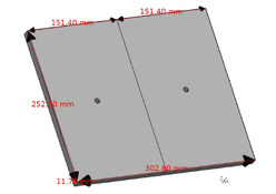
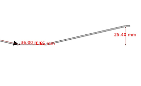
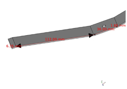
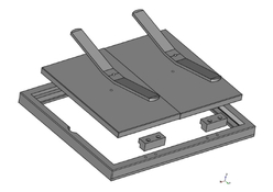
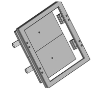
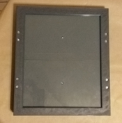
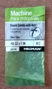
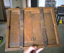
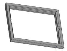
This is a new thread based on the linked thread, where this project originated. A new thread was decided upon for the highest visibility in the search engines. While I have not actually printed one, I have made test prints of sections, just to check for fit. I'm confident users will be able to print one out and use it. If there are complaints, please post them here. This was done in Freecad 21.2. These are stl files only, along with the PDF exports converted to JPEG for the woodworkers out there, although I strongly urge that it not be done in woodwork. The long and short rails are entirely different. On a Neptune 4 Max printer it requires only 15 1/2 hours for the frame alone, with a 50% infill with PETG filament. The glass is 3/32 ordinary picture frame glass, size 10 x 12 exactly. Since this frame is most likely to be taken out in the bright hot sun, DO NOT use PLA as it will surely melt. I'm sorry I couldn't post the actual Freecad files so that users could make changes, but apparently Freecad files won't zip. Measurements of my original antique Century 10 x 12 frame were taken on a metric Mitutoyo dial caliper. Moderators are asked to move the thread to wherever highest search engine visibility will allow
Linked original thread:

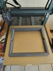
PS. Print frame backside up. No support or brim

{Moderator's edit - see post #25 for updated STL files}
 

Attachments

  • frame 3.stl.zip
    178.9 KB · Views: 35
  • frame.jpg
    frame.jpg
    806.1 KB · Views: 49
  • frame 3.jpg
    frame 3.jpg
    66.4 KB · Views: 49
Last edited by a moderator:
OP
OP
F4U

F4U

Member
Joined
Jan 15, 2025
Messages
495
Location
Florida
Format
8x10 Format
Here is the hinged back with holes, countersunk for 8-32 pan head, length unsure. Perhaps 1 inch. Print 2 of them, counterbored side up. No support. For the frame, no holes were marked or drilled in them. Perhaps fender washers will do. Spring steel dimensions to follow.
 

Attachments

  • hinged back w holes.jpg
    hinged back w holes.jpg
    61.3 KB · Views: 35
  • hinged back w holes.stl.zip
    103.5 KB · Views: 30

BrianShaw

Member
Joined
Nov 30, 2005
Messages
16,539
Location
La-la-land
Format
Multi Format
This is a very generous contribution, kind sir. (Now I need to buy a printer and learn how to use it.)
 
OP
OP
F4U

F4U

Member
Joined
Jan 15, 2025
Messages
495
Location
Florida
Format
8x10 Format
There is no charge on this. I give all rights to the Photrio board. If they want to charge, it's their business.
I have 2 printers. An Ender 3 original (not V2 or Pro), and a Neptune 4 Max. The Neptune 4 would do this fine. My Ender 3, it's small but has been a workhorse. Now I keep a .2mm nozzle on it and use it for threads, fine lettering, and tight tolerances. I can print filter threads so fine you need a magnifier to see them. Learning the printer is child's play, and they're not expensive. The hard part is learning Freecad. But if you're going to buy a piano, you have to study reading the music. But you'd be surprised the stuff I was making in Sept '22, 2 months after I bought the Ender 3. Never saw a 3D printer in my life before.
 
Last edited:
OP
OP
F4U

F4U

Member
Joined
Jan 15, 2025
Messages
495
Location
Florida
Format
8x10 Format
OK, here is where the project gets a little tougher. I have no idea where to get any spring steel stock 1 inch wide by 1.65mm thick. But here is how it is to be bent, using the 8-32 holes in the back as pivot points. These measurements are pretty exact, But remember, this frame was made 100 years ago or more. You will note in the photo where the ends are rounded, whereas they are not in my Freecad diagram. You'll have to file or grind the rounded ends on your own. Notice how my original one isn't terribly exact in the first place. Some people may find this part of the project a dealbreaker. But it occurs to me that maybe the spring steel part may not be necessary. Another way might be a couple blocks in the center of each half of the hinged back with very strong rubber bands stretched across screws on the outside edges of the frame. Won't be as strong. But all you're trying to do is keep a piece of sheet film in contact with paper. You're not trying to hydraulic press an automobile fender out of sheet metal.
Maybe I'll whip up couple blocks, put screw threads in the edges of the frame to hook rubber bands to, and make some leg rails so it'll still lay flat on an enlarger baseboard.
 

Attachments

  • spring steel photo.jpg
    spring steel photo.jpg
    805.3 KB · Views: 34
  • spring steel 2.jpg
    spring steel 2.jpg
    25.3 KB · Views: 35
  • spring steel.jpg
    spring steel.jpg
    40.3 KB · Views: 38

Don_ih

Member
Joined
Jan 24, 2021
Messages
7,808
Location
Ontario
Format
35mm RF
You don't need springs. Design your frame with an angled groove that the sliding bar can be pushed into to exert more clamping force.
 
OP
OP
F4U

F4U

Member
Joined
Jan 15, 2025
Messages
495
Location
Florida
Format
8x10 Format
You don't need springs. Design your frame with an angled groove that the sliding bar can be pushed into to exert more clamping force.
I'm afraid I can't visualize what you are describing. Perhaps you can scribble a picture, scan it and post it. Many of these people likely don't want to get into any kind of metal working. It's so much easier to sick a thumb drive into the printer and wake up next morning with the whole thing ready to use. Including me. The design I posted is merely a reverse-engineered copy of my old Century frame.
 

koraks

Moderator
Moderator
Joined
Nov 29, 2018
Messages
23,115
Location
Europe
Format
Multi Format
Perhaps you can scribble a picture, scan it and post it.

I think he means something along these lines, conceptually speaking:
1740212420091.png

I didn't feel like drawing it in CAD or figuring out construction details, so I just captured the concept as I understand it. Blue is a crossbar that pivots on a central point that's attached to the hinged back (back plate not shown). The crossbar has a thin lug on each end. The frame itself has a recess in both sides in which a wedge-shaped part sits. The crossbar's lugs are pressed into the recess in the frame. By swiveling the crossbar further, the end lugs are pressed down deeper 'into' the frame, making the crossbar exert more pressure on the pivot point and thus the back.

Like I said, no engineering or material details in the sketch above; there are several ways of doing this. I don't think any metal work is required apart from picking a couple of suitable parts from the nearest hardware store. The wedge-shaped bit doesn't even have to be a proper wedge; it can be something sufficiently sturdy sitting at an angle in the frame.

You can even do the whole thing without a rotating pivot; just have the crossbar push into these types of wedges slots on both ends of the frame in the same direction; push further for more pressure.

Nothing in this design relies on the flexibility of a material (e.g. spring steel) or is mechanically loaded in such a way that it'll pop into the face/hands of the user upon releasing. It's easy to construct in any of a number of ways. It's a smart concept.

Many of these people likely don't want to get into any kind of metal working. It's so much easier to sick a thumb drive into the printer and wake up next morning with the whole thing ready to use.

If all you have is a hammer...3D printing is great for any number of bits & bobs, but for printing a contact frame, I personally don't find it a logical choice. But that's not to discourage anyone from doing so.
 

Don_ih

Member
Joined
Jan 24, 2021
Messages
7,808
Location
Ontario
Format
35mm RF
You can even do the whole thing without a rotating pivot; just have the crossbar push into these types of wedges slots on both ends of the frame in the same direction; push further for more pressure.

That's right - and I didn't think a pivot point was necessary. Those green wedges can be integrated into the 3d printing design (not as steep as you've drawn them, and not penetrating the outside of the frame). The bar spans the inside width plus the depth of those slots - and I thought two bars would be best (one at 2/5 of the way from each end of the frame). Such a thing doesn't need to exert a lot of clamping force to do it's job.

(The advantage of having pivots would be the bars would always be attached.)

3D printing is great for any number of bits & bobs, but for printing a contact frame, I personally don't find it a logical choice.

I wouldn't do it, either, but I'm fully capable of making any number of things from wood and/or metal. After seeing what someone said in the other thread, I think a piece of glass spring clamped to a piece of plywood would probably do the trick just as well - for those with neither the skill to make things nor a 3d printer.
 

koraks

Moderator
Moderator
Joined
Nov 29, 2018
Messages
23,115
Location
Europe
Format
Multi Format
That's right - and I didn't think a pivot point was necessary.

No, it's not; the advantage of the pivot is indeed as you say the bars and the pressure plate become a single assembly, and applying pressure is a matter of a single twist on the bar. But a loose bar that you simply push underneath the wedges works fine as well. That's more or less how I use my smaller frame as well, although in my case, the bars lock underneath a flat metal protrusion and the pressure is applied by separate wedges. The concept is similar in that the pressure is created by a bar pressing down on the back and te pressure being governed by a wedge. There are so many ways of doing this; they all have their own pros & cons.

a piece of glass spring clamped to a piece of plywood would probably do the trick just as well

Yes, in principle it does, and I used to do it that way, too, but moved away from it because:
* The clamps take space, so you need a larger glass plate to allow for the clamps
* On larger surfaces, clamps tend to not work very well due to the flexibility of the materials (even glass!); it's hard to get really good contact, which depending on the printing process can be a problem (dot-based processes are particularly challenging.)
* Some processes use materials that are pretty difficult to clamp down effectively. I ran into major problems with carbon transfer because gelatin is so damn wayward especially if it's very dry. The force with which a gelatin-coated sheet curls is surprisingly strong.
* A frame is generally nice to set/lay down; something with clamps tends to balance on the clamps themselves; this can be cumbersome, especially because...
*...in terms of usability, clamping the whole thing down is cumbersome - you have to clamp in several places (generally four or even more, for very small prints and powerful clamps maybe two if you're lucky) and it's just a chore doing that every time. Might be OK if you do one print per day, but if you're doing linearizations or other forms of testing, the clamping routine gets old pretty quickly.

So yes, it does work in principle, but a decent frame is so much nicer to work with.
 

Don_ih

Member
Joined
Jan 24, 2021
Messages
7,808
Location
Ontario
Format
35mm RF
A clamped up piece of glass is not ideal, but it would be fine for the majority of people doing straightforward things like cyanotype and salt printing - or any other process where the paper is going to be mostly free of distortion and not heavily coated. It's especially good for someone who might do a few cyanotypes and then never do anything else like it.

But if I was going to do any amount of such printing, I'd want a good frame.
 

grahamp

Subscriber
Joined
Mar 2, 2004
Messages
1,708
Location
Vallejo (SF Bay Area)
Format
Multi Format
I am not sure that any regular filament is going to have enough stiffness for the common rotating spring bar clamps. PLA is the stiffest material (though it has one of the lowest glassing temperatures), and even that will flex a fair bit. Using a lot of walls, say 5mm, may be enough, though I'd probably look at embedding some steel bar in the frame. I don't have a printer that could handle this size, but I have done work up to 250mm, and learnt about material stiffness in practice. The frame profile does allow for a a lot of walls.

If you look at some of the commercial frames they use rotating short spring steel arms on the back usually 4, and it might pay to cannibalize one for the springs.

I do most of my contacting up to 8x10 using an old contact printer. The heavy glass is hinged at one end, with a clip at the other. Pressure is provided by some dense foam. Not ideal for doing inspection, though.
 
OP
OP
F4U

F4U

Member
Joined
Jan 15, 2025
Messages
495
Location
Florida
Format
8x10 Format
You won't need any steel embedded in the frame. I know the strength and limitations of 3D print by now. The frame and back will be just fine. Here is the first prototype of the printed spring made to the exact dimensions of the original metal one. Quite weak, as I knew it would be. I'll have a redesign directly that will work. In almost 3 years of this I've always found a way. Stand by.
 

Attachments

  • spring.jpg
    spring.jpg
    352.8 KB · Views: 38
OP
OP
F4U

F4U

Member
Joined
Jan 15, 2025
Messages
495
Location
Florida
Format
8x10 Format
Well here's the spring. In retrospect I suppose I should have waited till I had a finished final item to bring to the forum. I had no idea I'd go through an evolution on it. But here's my spring, after 5 redesigns and 3 prototypes. It's made of PETG, which I just bought a roll of for the first time. Looks like my PLA days are over. This stuff prints nice. Strong, and doesn't melt in the hot sun. I bet this spring will last a very long time. And I believe from playing with it that it actually has a hair more spring pressure than the original metal one. I wonder if anybody out there has already downloaded and printed the frame and back? I believe I'll design a retro-fit to that one, rather than a complete re-design. The entire unit will be 3D print, requiring only a few ordinary screws, nuts, and washers available at any hardware dept. If someone can put a new plug on a lamp-cord (which a certain brother-in-law I know of can not), they can put together this frame and use it trouble free the rest of their life. Stand by for the final proejct. Thank you.
 

Attachments

  • spring  final.jpg
    spring final.jpg
    869.4 KB · Views: 33
  • PETG spring.jpg
    PETG spring.jpg
    29.3 KB · Views: 34
OP
OP
F4U

F4U

Member
Joined
Jan 15, 2025
Messages
495
Location
Florida
Format
8x10 Format
Attention: I don't know if anybody has made one of these frames from the stl's Ive provided. If so, they will be OK. Since then I have perfected these designs without drastically changing anything. I've decided to order a roll of gray PETG, as all I have is black. PLA would have worked fine, but there was always a danger someone might take it out in the hot sun and returned to their salt print or cyanotype and find their frame warped. PETG is somewhat more resistant to this. But since I only have black, I'm ordering gray. No use in pushing my luck. Black anything gets HOT.
After the gray filament gets here I will make a final proof of my own, and then release all files to be posted. If you like these alternate printing processes, I'm sure you will be very happy with your new frame. Give me a week or so to get the filament in here and a couple days to print. Regards.
 
OP
OP
F4U

F4U

Member
Joined
Jan 15, 2025
Messages
495
Location
Florida
Format
8x10 Format
Well here it is, all ready to print. Been working on it all week. This design does not obsolete the previous one in any way. It's simply been refined and upgraded. I licked the problem of the springs. These PETG pastic ones are actually a bit stronger than the original spring steel ones, and seem to hold up very well after pushing down on the ends of a prototype I made about a jillion times this week. I even heated the spring up in the oven to 150F. After 30 minutes and it fell flat as a pancake. But as soon as I took it out, I bent it back up again quickly and it was good as new. At 125F it still holds up pretty well although pushing down on it that hot a few times causes a partial loss of pressure. At 100 degrees it's fine. Are any of us going to go outside to make contact prints in 100 degree weather? Not me. But you can. I'm happy enough with the spring.
The hardware is eight 8-32 x1.5 inch screws and nuts and two 6-32 x 3/4 screws and nuts, and a cheap 10x12 picture frame, robbed of its glass, and a 10x12 piece of felt. My gray PETG filament came in, so now I'll print my prototype. That ought to take a couple days, at least. If all goes well I'll post the stl files.
 

Attachments

  • frame done.jpg
    frame done.jpg
    78.3 KB · Views: 35
  • frame 2.jpg
    frame 2.jpg
    67.2 KB · Views: 37
OP
OP
F4U

F4U

Member
Joined
Jan 15, 2025
Messages
495
Location
Florida
Format
8x10 Format
The frame is back there in the radio room, printing as we speak. Today I went to the hardware store and got the planned screws, wihch they had and Lowes did not (typical). And Wal Mart (which I hate) had no 10 x 12 picture frames. I learned that cheap picture frames come in 8x10, 8 1/2x11, and 11x14, but not 10x12. Fortunately there are still a few hardware stores gasping for breath to keep living another day. THEY cut me a 10x12 piece of glass. Had I known that, I'd have made the frame 11x14. The whole idea was to design the thing so that people could make one from commonly available inexpensive items.
 

BrianShaw

Member
Joined
Nov 30, 2005
Messages
16,539
Location
La-la-land
Format
Multi Format
11x14 would be great. Does your CAD software have an enlarge button? 😝
 
OP
OP
F4U

F4U

Member
Joined
Jan 15, 2025
Messages
495
Location
Florida
Format
8x10 Format
I use Freead, because of 3 reasons: It's good, it's free, and I'm a cheapskate. You can open things in the Draft workbench and clone it, which will give you an opportunity to change sizes, but only allows 2 digits after the decimal point. I've found that often times that's not enough accuracy. And it doesn't often work out that way, especially if you have designed things in them like screw threads or for things or hardware with set sizes. The best way is to go back to Part Design or Part Workbenches (whichever one you did it in) and modify the constraints. By that time It might be easier to design a whole new item.
 
OP
OP
F4U

F4U

Member
Joined
Jan 15, 2025
Messages
495
Location
Florida
Format
8x10 Format
Well here is the frame when it was cooling on the print bed. It turns out I got all my measurements right on the nose, including something I didn't like, which I've since gone back in the file and corrected. The hardware store cut the glass to a perfect 9x12, but the frame opening is a hair too big to give the glass good support in all 4 directions. No big deal. If I used my old wooden one all the years with no problem, this one will do fine--for me. But for you guys I gave the glass an additional support of 2mm in each direction. These springs I designed seem to be able to put a pretty good smash on the negative-and-paper sandwich. Remember the glass is only 3/32. Thinking back to a previous post about people using heavy, wavy paper for cyanotypes, I believe an 11 x 14 frame with 1/4 inch plate glass and 4 of these springs would be best, so you can REALLY put the smash on it. Give me the rest of the weekend to print all the other parts and road-test it before posting files.
 

Attachments

  • on print bed.jpg
    on print bed.jpg
    767.1 KB · Views: 36
OP
OP
F4U

F4U

Member
Joined
Jan 15, 2025
Messages
495
Location
Florida
Format
8x10 Format
Here it is, just finished. Everything turned out as I'd hoped. I'll put my print files together and post the stl's tomorrow.
 

Attachments

  • 1.jpg
    1.jpg
    665.2 KB · Views: 46
  • 2.jpg
    2.jpg
    669.2 KB · Views: 46
  • 3.jpg
    3.jpg
    508.2 KB · Views: 43
OP
OP
F4U

F4U

Member
Joined
Jan 15, 2025
Messages
495
Location
Florida
Format
8x10 Format
Here are the stl's for the finished frame. Note to moderators: Please edit the first post to point people down to this post for the files they need. Instructions: Print items in light colored PETG, NOT PLA. This frame was intended for use in the hot mid day sun where PLA will warp. ABS might be even better for heat resistance but I never had much luck with ABS staying stuck to the print bed. Total amount of filament usage for the entire job is about 1 1/3 rolls of filament. Frame: 55% infill, word Photrio facing upwards. Use support touching buildplate . Pry out hexagonal holes for nut recess. Backs: Files are labeled 1 and 2. Print one of each Photrio side up, 40% infill at least. Support touching buildplate. Pry out support for head of screw pocket. Springs: Print two of them. They are identical, 85% infill, no support, use PETG, as it seems to keep its spring strength. Feet :4 of them printed on end with raft support only, 35% infill. Hardware: Eight of 8-32 x 1 12 screws and nuts. I used brand pictured, from Lowes. Other brands may nt have same size nut exterior diameter. If yours are too big, use hot soldering iron to push them down in the countersunk pockets. For the springs use two 8-32 x 1" screws, washers, and 8-32 locknuts. Glass: 9x12 x 3/32 ordinary window glass. Frame storage when not in use: recommend storing with springs relaxed. If at any time you notice them losing their strength, dis-mount them and place them in 150F oven for 20-30 minutes and re-bend quickly. They'll only stay soft for 5 seconds. The holes were for the hinges i bought. Yours may be differernt. In that case, drill your own holes. Glue in the screws to them
The springs seem to be quite strong in PETG. Cover pressure-side of hinged back with red, orange or yellow felt. NO black. I have not posted these on any other site. I consider them Photrio property. If they want to post them for money on a third party site, that's their affair.

Edit, important. When printing springs, be sure to print them on edge, not flat. Use raft. no oher support.
 

Attachments

  • Photrio frame.zip
    673.3 KB · Views: 32
  • screws.jpg
    screws.jpg
    963 KB · Views: 30
Last edited:
Photrio.com contains affiliate links to products. We may receive a commission for purchases made through these links.
To read our full affiliate disclosure statement please click Here.

PHOTRIO PARTNERS EQUALLY FUNDING OUR COMMUNITY:


Ilford ADOX Freestyle Photographic Stearman Press Weldon Color Lab Blue Moon Camera & Machine
Top Bottom