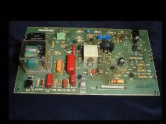
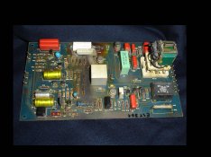
Circuit needed for Durst power supplies EST 301 and EST 450

mirrorculous

A
mirrorculous

  • 2
  • 0
  • 358
The Lady In Black

A
The Lady In Black

  • 0
  • 0
  • 561
Lady in Black

A
Lady in Black

  • 5
  • 0
  • 635
Mangrove Bend

A
Mangrove Bend

  • 4
  • 1
  • 1K
Sonatas XII-58 (Life)

A
Sonatas XII-58 (Life)

  • 0
  • 1
  • 1K

Forum statistics

Threads
199,874
Messages
2,797,955
Members
100,063
Latest member
Uldis UĶ
Recent bookmarks
0

Jose Velez

Member
Joined
Mar 1, 2005
Messages
7
Location
near Lisbon,
Format
Large Format
Hi everybody,
I'm trying to repair two Durst power supplies from a friend, respectively an EST 301 and an EST 450.
I checked already the regulator board of the ES301 and it's clear that the PCB contacts of the current sensing resistors R42 and R43 and severely burned. There is a group of resistors nearby which I would like to substitute also, but it's no longer possible to read the respective value, as they have darkened considerably, like the surrounding PCB.

I didn't open the EST 450 yet, but I may likely find a similar situation, therefore I will be grateful if someone can provide me the respective schematics.

Thank you in advance,
Jose
 

ic-racer

Member
Joined
Feb 25, 2007
Messages
16,633
Location
USA
Format
Multi Format
Quote from the following thread:
I have to thank once again fellow Georges Giralt for sending me the EST 450 tech manual complete with schematics, that although written in mixed french/german has been extremely useful in understanding this complicated machine.

(there was a url link here which no longer exists)
 

cferrari

Member
Joined
Mar 23, 2009
Messages
4
Location
Brighton, En
Format
Medium Format
Jose,

I have just got hold of an EST450 which I wasn't sure was working properly, and so had it apart, and can provide photos of the circuit. My one appears to be one of the later ones - the board is clean, but has some odd features (shorted out tracks on the back) which i'm not sure are original.

Let me know if you want pictures, I can provide these and traces from the supply in use.

6993333758_715f9753d0_b.jpg
 

ic-racer

Member
Joined
Feb 25, 2007
Messages
16,633
Location
USA
Format
Multi Format
but has some odd features (shorted out tracks on the back) which i'm not sure are original.
A couple of the Durst printed circuit boards I worked on have similar features. I believe those were to update the circuit. In one case the changes matched a 'circuit update' note on one of the schematics.
 

cferrari

Member
Joined
Mar 23, 2009
Messages
4
Location
Brighton, En
Format
Medium Format
A couple of the Durst printed circuit boards I worked on have similar features. I believe those were to update the circuit. In one case the changes matched a 'circuit update' note on one of the schematics.

Ah, ok, thanks for that. I'm still wary of this transformer, it's also got a pair of 1 ohm resistors in series with the transformer on the power side, and these are of different makes and are glued to one end of the transformer (I guess with it acting as a heat sink). It's all a bit heath robinson compared to the rest of the design. I guess this could also be a circuit update as i've heard that they had a fairly high failure rate with this power supply....

I've measured the light output of my L1200 with this supply and compared it to the output from a standard TRA450 and they are within measurement tolerance so it does appear to work in it's current form. I guess I should run it for 1/2 an hour and keep an eye on the temp on these extra components to ensure they don't melt a hole in the case ;-)
 
OP
OP

Jose Velez

Member
Joined
Mar 1, 2005
Messages
7
Location
near Lisbon,
Format
Large Format
Hi cferrari,
Thanks you for the support, but apparently the ones I'm trying to fix are much older, below you can see pictures of both regulator cards:

EST 450 board:
EST_450.jpg

EST 301 board:
EST_301.jpg
 

ic-racer

Member
Joined
Feb 25, 2007
Messages
16,633
Location
USA
Format
Multi Format
but it's no longer possible to read the respective value, as they have darkened considerably, like the surrounding PCB.

Have you measured them? Looks like it just might be surface damage on those resistors from the 'flames' thrown by the power resistor when it went bad.

Were you able to contact Georges Giralt for the schematic?
 
OP
OP

Jose Velez

Member
Joined
Mar 1, 2005
Messages
7
Location
near Lisbon,
Format
Large Format
Have you measured them? Looks like it just might be surface damage on those resistors from the 'flames' thrown by the power resistor when it went bad.

Were you able to contact Georges Giralt for the schematic?

Hi,
I did not touch the 301 yet, but I'm also hoping that it is more "smoke than fire", literally.
On the 450 I replaced the electrolytic capacitors and a burned resistor, but I must investigate further because the regulating transistor is driving too much current and burned again the resistor.

I already sent a PM to Mr. Giralt (only one day ago, no answer yet). Hopefully he will be able to help me, as following the circuit without the schematics is much harder.

Thanks, best regards.
Jose
 

ath

Member
Joined
Aug 29, 2006
Messages
844
Location
Germany
Format
35mm
When the epoxy in the board gets brown or even black it stops to isolate and starts to conduct.
A board like the 301 is probably beyond repair.
Both look to be from the early 70ies, probably a good idea to replace all electrolytic capacitors.
 

Blurryimages

Member
Joined
May 7, 2016
Messages
16
Location
London
Format
Medium Format
Hi All,

Similarly to some of you, I also have a problem with my EST 450 stabiliser. After opening it I've found that resistor R-42 (causing darkened/burned area around it) is heating extremely and I think it can cause that enlarger has stopping to turn off once timer goes to 0 seconds - light is still on. Can anyone advise where in England or anywhere in Europe, I can wing it to repair? Very useful would be to obtain its electrical diagram as I know very good electrician but without this diagram he won't be able to help I'm sure.

Any information appreciated, especially with diagram. I'm sure someone has it! :smile:
 

ruilourosa

Member
Joined
Apr 13, 2003
Messages
797
Location
Portugal
Format
Multi Format
Can i use a 24v 10 or 15 amps led driver? as a substitute?


i do not have the original est 450 or tra 450...
 

ic-racer

Member
Joined
Feb 25, 2007
Messages
16,633
Location
USA
Format
Multi Format
I think a 24v transformer makes a more straight-forward solution than a switching power supply, but that is just me (and Durst).
Screen Shot 2019-03-11 at 4.23.06 PM.png
 
Joined
Jun 7, 2005
Messages
801
Location
Torino, Italy
Format
Large Format
I think that most Durst enlarger heads of that power (if not all of them) had forced-air venting, so remember to supply electricity also to the fan or the head will overheat.
 

mgb74

Subscriber
Joined
Jan 24, 2005
Messages
4,778
Location
MN and MA US
Format
Multi Format
A friend recently acquired a CLS 450 without transformer. He's interested in have a transformer built for him if he can't find one.

From my VERY limited knowledge, it looks like you have constant 25v going to the colorhead for it's fan and electronics plus switched 25v (controlled by timer) going to the lamp.

Is the design straightforward enough that so it can be replicated from the schematic? And are the components common enough to acquire off the shelf? The other question is whether there is any voltage stabilization in this design.
 

ic-racer

Member
Joined
Feb 25, 2007
Messages
16,633
Location
USA
Format
Multi Format
The circuit is easy to reproduce. The difficult part is making a safe box with safe connectors and plugs. Some contraption without a box and exposed wires hanging off it could be a fire risk in a 'dark room.'
 

mgb74

Subscriber
Joined
Jan 24, 2005
Messages
4,778
Location
MN and MA US
Format
Multi Format
The circuit is easy to reproduce. The difficult part is making a safe box with safe connectors and plugs. Some contraption without a box and exposed wires hanging off it could be a fire risk in a 'dark room.'

The enclosure should be easy enough for the "dry" side. Thanks.
 

Chan Tran

Subscriber
Joined
May 10, 2006
Messages
6,956
Location
Sachse, TX
Format
35mm
Depending on the output needed I would rather simply buy a regulated 24VDC power supply.
 

warmtone

Member
Joined
May 6, 2005
Messages
19
Location
Melbourne, Australia
Format
Multi Format
Hi Everyone who has a Durst Laborator 1000/CLS450 and stabiliser EST 450 may be interested in the attached information** that provides a circuit diagram and description of operation.
I have never found this level of information on the internet - I got hold of it some years ago from the Durst dealer in Sydney Australia.

These are complex units with high voltages floating around - beware of the "hot" heatsink that houses the main Triac if you need to fix a fault.

If you are not technically qualified do not attempt fault fixing - leave this to someone who is because - "the high voltages inside are utterly capable of taking you to the heavens"

For those who are qualified, its a load of fun tracing through what is a very sophisticated but overly complex design.
When working properly it does a fine job of achieving regulated 23.5V at the globe and protection during start up - with globe short circuit protection as well.
These units are still worth fixing as most components are readily available and they last a long time when sorted out.

Mine has developed a weird problem with the light output oscillating - if anyone has fixed this fault advice welcome.

**PS Cannot load the document it is too large - I will try and crunch it down
 
Last edited:

AgX

Member
Joined
Apr 5, 2007
Messages
29,973
Location
Germany
Format
Multi Format
Do mean that heat sink is carrying voltage by design?

(Your wording "hot" is ambiguous to non-native speakers in this case.)
 

warmtone

Member
Joined
May 6, 2005
Messages
19
Location
Melbourne, Australia
Format
Multi Format
Hi AGX re the heatsink; the EST 450 Manual warns it is under ‘full mains voltage“ - which I doubt looking at the circuit but it does carry sufficiently high AC voltage to be lethal.
Hot In this context means “Live and Dangerous”. Due to the close proximity between the live heatsink and PC board extra care is needed When taking measurements.
 

warmtone

Member
Joined
May 6, 2005
Messages
19
Location
Melbourne, Australia
Format
Multi Format
Another question would be if voltage stabilisation is needed at all.
Voltage stabilisation is necessary to a) prolong the life of the bulb and b) provide consistent light output during exposure.
A non regulated solution will generally reduce the life of the globe and cause unpredictable light output due to mains fluctuation, temperature changes and even length of exposure.
If you want control and predictable results a properly designed stabiliser is essential.
 

AgX

Member
Joined
Apr 5, 2007
Messages
29,973
Location
Germany
Format
Multi Format
If the mains voltage is stable there is no need for a voltage stabilizer.

And to prolong the life of an incandescent lamp, in first instance it has to be run not at too high nominal voltage. If a voltage regulator can achieve this that is fine. However a classic magnetic stabilizer will not. Here then a variac is the way to go.

Another important way to prolong the life of an incandescant lamp is to reduce/limit current at switching on of the lamp. A voltage stabilizer will not do that.
 

warmtone

Member
Joined
May 6, 2005
Messages
19
Location
Melbourne, Australia
Format
Multi Format
If what you are saying is correct Durst would not have bothered manufacturing the EST450.

Facts:
Mains voltage can fluctuate by 10% + and directly affect light output with no regulation
The resistance of the bulb is non linear and changes with temperature and length of exposure causing light output to change (drift)
The EST 450 has a ‘warm up” function that limits current to the bulb for about 25 seconds to preserve life expectancy (50 hours)
The EST 450 When adjusted correctly maintains the bulb voltage close to 23.5v to preserve its life and maintain stable light output

The Durst Laborator 1000 was designed for professional use and demanding colour printing where Light output control and repeatability is essential.
For photographers pursuing the fine print in B&W photography the sane level of control is also generally required.

But if you don’t need any of the the above benefits a non regulated solution is fine.
 
Last edited:

AgX

Member
Joined
Apr 5, 2007
Messages
29,973
Location
Germany
Format
Multi Format
A major issue in discussions as these is the term voltage stabiliser as various devices can be subsumized.

My mains voltage variations metered over weeks is below 1%.

In case the mains voltage is stable. a great lot of possible issues can coped with by just having the lamp burn all time and use a shutter. A seperate shutter device was on the market but obviously not successful. (never read about it again). Here is the advatage of enlargers with incorporated shutter

Another issue is the different behaviour between plain and halogen incandescent lamps, with the plain ones having their resistance rise over their lifetime and thus their colour temperature fall.
 
Photrio.com contains affiliate links to products. We may receive a commission for purchases made through these links.
To read our full affiliate disclosure statement please click Here.

PHOTRIO PARTNERS EQUALLY FUNDING OUR COMMUNITY:


Ilford ADOX Freestyle Photographic Stearman Press Weldon Color Lab Blue Moon Camera & Machine
Top Bottom