• Welcome to Photrio!
    Registration is fast and free. Join today to unlock search, see fewer ads, and access all forum features.
    Click here to sign up

Chromegatrol timing circuit repair

Recent Classifieds

Forum statistics

Threads
201,760
Messages
2,829,664
Members
100,929
Latest member
WBM
Recent bookmarks
0

pwadoc

Member
Allowing Ads
Joined
Mar 12, 2019
Messages
98
Location
Brooklyn
Format
Multi Format
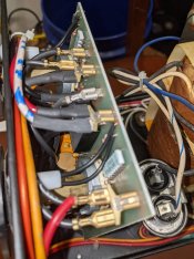
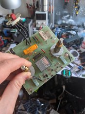
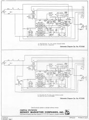
Hey all, I recently inherited a Chromegatrol (version 412-040) power supply and timer for Super Chromega D enlarger that is exhibiting the classic symptoms of a problem with the timing circuit: the enlarging bulb doesn't light and the unit emits a strange buzz. I opened the thing up and looked for obvious damage but it actually seems pretty clean inside. I ended up labeling all the connections and pulling the board so that I can check/replace all of the components (starting the with the big electrolytic capacitor), but I'm wondering if anyone who has done this repair has any suggestions for a specific culprit. I took a video of the behavior (http://ur.sine.com/temp/PXL_20210225_040409931.mp4) so you can see what's going on. I'm also puzzled about the big aluminum cylinder (in the bottom right of the first image) in the housing. Is it a relay? A giant capacitor? I think it's labeled on the schematic as DS1 and DS2 (never mind I realized these are the indicator lamps, so I have no idea where it is on the schematic), since I don't see anything else on there it could be, but the symbol is equally inscrutable. Any help or advice is appreciated!
 

Attachments

  • PXL_20210225_040506692.jpg
    PXL_20210225_040506692.jpg
    891.5 KB · Views: 184
  • PXL_20210226_174120178.jpg
    PXL_20210226_174120178.jpg
    839.5 KB · Views: 158
  • chromegatrol-schema.jpg
    chromegatrol-schema.jpg
    811.3 KB · Views: 221
Last edited:

DWThomas

Subscriber
Joined
Jun 13, 2006
Messages
4,623
Location
SE Pennsylvania
Format
Multi Format
The big can at the lower right looks like the connection end of a capacitor. A similar can appears in various equipment for starting or split phase running an AC motor. (I just replaced one in my 12" radial arm saw.) Since you mentioned buzzing, that cap could possibly be a culprit -- but I have no idea what the rest of your circuit looks like.
 
Last edited:
OP
OP
pwadoc

pwadoc

Member
Allowing Ads
Joined
Mar 12, 2019
Messages
98
Location
Brooklyn
Format
Multi Format
The big can at the lower right looks like the connection end of a capacitor. A similar can appears in various equipment for starting or split phase running an AC motor. (I just replaced one in my 12" radial arm saw.) Since you mentioned buzzing, that cap could possibly be a culprit -- but I have no idea what the rest of your circuit looks like.

Looking at the schematic (forgot to add that to the first post, should be there now) again, I think you're right. I missed the cap labeled C6. I've never seen one that size, but I'm gonna guess it's a #1 culprit for this type of failure. Thank you!
 

DWThomas

Subscriber
Joined
Jun 13, 2006
Messages
4,623
Location
SE Pennsylvania
Format
Multi Format
Looking at the schematic (forgot to add that to the first post, should be there now) again, I think you're right. I missed the cap labeled C6. I've never seen one that size, but I'm gonna guess it's a #1 culprit for this type of failure. Thank you!
Ah yeah, it appears that unit has a ferro-resonant constant voltage transformer which likely needs that cap working to operate. (My saw had both a start and a run cap and I got both off an Amazon merchant and replaced them for a total of about $23. The originals had 1973 date codes on them so I shan't complain!)
 
OP
OP
pwadoc

pwadoc

Member
Allowing Ads
Joined
Mar 12, 2019
Messages
98
Location
Brooklyn
Format
Multi Format
Ah yeah, it appears that unit has a ferro-resonant constant voltage transformer which likely needs that cap working to operate. (My saw had both a start and a run cap and I got both off an Amazon merchant and replaced them for a total of about $23. The originals had 1973 date codes on them so I shan't complain!)

Yeah, I think you're right. Also enjoying the complete lack of any isolation on a high voltage device intended to work around fluids.
 

ic-racer

Member
Joined
Feb 25, 2007
Messages
16,727
Location
USA
Format
Multi Format
You would not want an enlarger or its power source anywhere near fluids! The 'wet' side of a darkroom is traditionally separate in space from the 'dry' side.
 

ic-racer

Member
Joined
Feb 25, 2007
Messages
16,727
Location
USA
Format
Multi Format
To give you some encouragement to persist with your repairs. I made two of these D5500 power supply boards from ALL NEW parts. Including an integrated circuit that was available only from OMEGA (I bought the last ones they had). Yes, this was one of the most amazing things I have experienced. I called Omega Satter in 2009 and they had a box of UDN5714M (and integrated circuit unavailable anywhere) so I bought enough to fix two power supplies!
BTW; After replacing every component except the UDN5714M the power supplies were still non-functional, it was the UDN5714M that had failed in both.

Every component replaced with new, except the transformers an the R2 trimmer pot:

Finished Board.JPG
 
Photrio.com contains affiliate links to products. We may receive a commission for purchases made through these links.
To read our full affiliate disclosure statement please click Here.

PHOTRIO PARTNERS EQUALLY FUNDING OUR COMMUNITY:


Ilford ADOX Freestyle Photographic Stearman Press Weldon Color Lab Blue Moon Camera & Machine
Top Bottom