Built My Own UV Lightbox for $30.

Curved Wall

A
Curved Wall

  • 3
  • 0
  • 61
Crossing beams

A
Crossing beams

  • 9
  • 1
  • 83
Shadow 2

A
Shadow 2

  • 3
  • 0
  • 60
Shadow 1

A
Shadow 1

  • 3
  • 0
  • 57
Darkroom c1972

A
Darkroom c1972

  • 3
  • 2
  • 104

Recent Classifieds

Forum statistics

Threads
198,837
Messages
2,781,626
Members
99,722
Latest member
Backfocus
Recent bookmarks
0

fgorga

Member
Joined
Aug 31, 2015
Messages
769
Location
New Hampshire
Format
Multi Format
No alt process needs UVC -- thank goodness. Most are highly sensitive to UVB, but is also hazoudous to work with. The glass of the contact printing frame would block 95% of the UVB and I believe all of the UVC. So we typically use UVA, with some variations in the processes as to sensitivity and wavelength.

This is correct... the shorter the wavelength the more hazardous the UV. UV-C the shortest wavelengths of UV and UV-A the longest consideed to be UV. UV-C is very hazardous to human health. It is germicidal because it damages DNA. It is not selective... it damages human DNA as well as bacterial or viral DNA. UV-C is a carcinogen and it causes acute damage to the eyes. Humans should not be exposed to UV-C. In situations where UV-C is used there are interlock mechanisms built into the devices to insure the lights go off before the door is opened... so to speak.

As for the transmission of UV through common materials. Glass will transmit some into the UV-B range, but not far. In the lab we would switch from glass to quartz if we needed good transmission below about 300 nm.

Incidentally, common clear plastics are essentially opaque to UV radiation, with transmission falling off very quickly below 400 nm to essentially zero by 300 nm. This includes acrylics (Plexiglass/Perspex) and polycarbonate (Lexan) which are sometimes used instead of glass for glazing. Thus, these glass substitutes are not useful for alternative process printing.
 

fgorga

Member
Joined
Aug 31, 2015
Messages
769
Location
New Hampshire
Format
Multi Format
I was watching a video on youtube today of someone who built their own UV box as well, but he split the LED strips into two banks to prevent voltage drop. After watching this I was tempted to test mine. They're supposed to be 12v but at the end of the very first strip I have a .5 drop, to 11.5v. Four strips down I have a voltage of 10.7, and by the very end of the entire bank I've got a reading of 9.5v.

This is at the least a 2v drop, or at the max a 2.5v drop.

I'm wondering if this is enough to worry about, and reason to rewire everything into two banks.

The other option is to order two more rolls and fill in the gaps, and start the bank opposite of the one that's already installed, to balance everything out.

The only way to,know for sure if this is a problem, will be to print something large enough to span your box and see if the exposure is uniform.

Given your previous posts about the longish exposure times, I might be inclined towards your second idea... adding more strips.
 

koraks

Moderator
Moderator
Joined
Nov 29, 2018
Messages
22,897
Location
Europe
Format
Multi Format
They're supposed to be 12v but at the end of the very first strip I have a .5 drop, to 11.5v. Four strips down I have a voltage of 10.7, and by the very end of the entire bank I've got a reading of 9.5v.
Can you post a schematic of how you wired them and indicate where you measured the voltages indicated above? What is the total power rating of the led strips combined and what is the rating of the power supply?
 
OP
OP
ChristopherCoy

ChristopherCoy

Subscriber
Joined
Aug 9, 2011
Messages
3,599
Location
On a boat.
Format
Multi Format
Can you post a schematic of how you wired them and indicate where you measured the voltages indicated above? What is the total power rating of the led strips combined and what is the rating of the power supply?

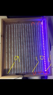
I can’t draw a schematic but I can show you. Essentially it’s wired as one long piece. Yellow is where I checked voltages.
2A21B155-61C2-4DA7-8859-1EF5797EA537.jpeg
 

koraks

Moderator
Moderator
Joined
Nov 29, 2018
Messages
22,897
Location
Europe
Format
Multi Format
Right, that's not optimal. The conductors in the strips have a non-negible resistance at these power levels. Wire the strips in parallel and the problem is likely gone.
 

Donald Qualls

Subscriber
Joined
Jan 19, 2005
Messages
12,295
Location
North Carolina
Format
Multi Format
When wired in series, all LEDs in a circuit see the same current, and will have the same drop across the LED, hence same output.

When wired in parallel, all will see the same voltage (assuming heavy enough wire is used), and will have the same drop across the LED, hence same output. Shouldn't make any difference to the LEDs.
 
OP
OP
ChristopherCoy

ChristopherCoy

Subscriber
Joined
Aug 9, 2011
Messages
3,599
Location
On a boat.
Format
Multi Format
Ok... next question....how do I wire them in parallel? Is that negative to positive and positive to negative?
 

koraks

Moderator
Moderator
Joined
Nov 29, 2018
Messages
22,897
Location
Europe
Format
Multi Format
When wired in series, all LEDs in a circuit see the same current, and will have the same drop across the LED, hence same output.

When wired in parallel, all will see the same voltage (assuming heavy enough wire is used), and will have the same drop across the LED, hence same output. Shouldn't make any difference to the LEDs.
Not quite. The led strips usually have 3 or 4 leds in series, sharing a single current limiting resistor. All those 3/4 led 'modules' are wired parallel between the +12V and the 0V lines on the strip. That's why there are cut marks on those strips, so that you don't inadvertently cut right through one of the 3/4 led groups.
So all these 3/4 led groups always see +12V no matter how the strips are wired - at least in theory. In practice, the conductors on the strips themselves of course have resistance, which makes for a voltage drop if the string is very long and fed in series, as is the case here.

Ok... next question....how do I wire them in parallel? Is that negative to positive and positive to negative?
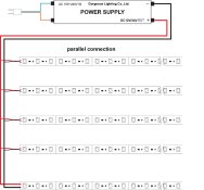
Not sure what you mean, but think of a 'star' layout. You connect all the 0V leads of all the strips to the 0V connector of the power supply, and all the +12V of the strips to the +12V of the power supply. This means a lot more wires than you have now, but it prevents the current having to make a round trip through all of those strips.
There are probably thousands of websites explaining this, and here's just one of them: https://ledgardener.com/wiring-led-cobs/
They're using COB modules but the principle is the same as with strips. Just regard each of your strips as a separate module.
 
Joined
Jul 31, 2012
Messages
3,352
Format
35mm RF
When I built my UV box I wired everything in parallel. I put a solid heavy copper wire down both sides then on one side I soldered the +, on the other side I soldered the -. Seemed to work out fine.

I also used a different power supply since I used three strings (about 90 feet). It is 12v 20a. I am not an electrical engineer, but the voltage is the same and I did some back of the napkin computin' and figured 20a aught to do it. It may be too much, but I also adjusted the voltage on the power source to a little less than 12v just to be sure. I've stuck my hand in there when it has been running and cant feel any heat. I also put four computer fans at one end to blow cool air through it but I doubt I needed that with the short times I get for exposures. I put the box on a Gralab timer when I print with it so it doesn't stay on. It has worked out far better than I anticipated with cyanotype times between a minute and a half and three minutes. Can't complain about that... Beats the 40 minutes I had back in the 90s when I did cyanotypes with a BLB setup.
 

Donald Qualls

Subscriber
Joined
Jan 19, 2005
Messages
12,295
Location
North Carolina
Format
Multi Format
sharing a single current limiting resistor.

And this is why you have a voltage drop when they're wired in series. Not the resistance of the conductors (which is negligible at reasonable current levels), but the current limiting resistances. Each strip you wire adds one of those, plus the voltage drop of the LEDs in that strip. The total drops (I*R for each limiting resistor, plus the drops of the LED network in each strip) will always add up to equal the supply voltage at operating current.

Wiring them in parallel makes a different demand on the power supply, too -- you'll add the currents for each string, instead of running the same current through all of them in sequence. If each string draws, say, 0.5A at 12V supply, and you have twelve strings, your power supply needs to put out 72W -- 6A at 12V. OTOH, if you're running those strings in series, you'd need only 0.5A -- but 144V to give every string its 12V. Still 72W, but 12V and 6A is a very different supply from 144V at 0.5A.
 
OP
OP
ChristopherCoy

ChristopherCoy

Subscriber
Joined
Aug 9, 2011
Messages
3,599
Location
On a boat.
Format
Multi Format
Ok parallel is what I thought.

A81F3521-617E-4064-B4E3-3B0ED15D39FC.jpeg

Now to actually sit down and figure out the best way to do it. A buss bar would be really helpful right about now.
 

Donald Qualls

Subscriber
Joined
Jan 19, 2005
Messages
12,295
Location
North Carolina
Format
Multi Format
For 12V and an amp or two, a cheap lamp extension cord ("zip cord") (from Dollar General, for instance) is plenty of current capacity. You can split ("zip") the cord apart where you need to make connections, strip a short section to solder, and wrap the stripped spot (individually) in electrical tape. Or you can zip the whole cord apart into separate wires, and slip heat-shrink on for each connection.
 

koraks

Moderator
Moderator
Joined
Nov 29, 2018
Messages
22,897
Location
Europe
Format
Multi Format
And this is why you have a voltage drop when they're wired in series
Nope, the resistors probably dissipate about 5-10% of the total power and will do so regardless of parallel or series connection of the strips. They have nothing to do with the voltage drop over the combined length of the series connected strips.

In your reasoning you're likely overseeing the fact that a led strip is typically a parallel connected array consisting of in turn series connected leds (usually 3), with each of these sub-arrays having their own series resistor. So the power draw will always be the same, and the supply voltage will also always be the same. This has obvious advantages during installation where you can't really expect that everyone will be able to work out the proper power requirements if it depends on strip length.

As I pointed out, the only obvious drawback is that the conductors in those strips really DO have a non-negligible resistance. You mentioned 'reasonable current levels', but that's exactly the issue. If you take a bunch of strips with a total power consumption of (let's say) 100W, that means 8A @ 12V. That's a lot of current to run through a thin strip.
 
Last edited:

Donald Qualls

Subscriber
Joined
Jan 19, 2005
Messages
12,295
Location
North Carolina
Format
Multi Format
Okay, you're saying that each LED has its own current limiting resistor, I think.

As you say, though, if the wiring is undersize you can have the wiring dissipating significant power, hence dropping voltage over its length. Definition of undersize wiring? It dissipates significant power in the copper. I agree, 8A is pretty heavy current if the wire is smaller than 18ga equivalent. Like trying to run a milk house heater through a lamp cord: cord heats up almost as much as the heater elements.
 

koraks

Moderator
Moderator
Joined
Nov 29, 2018
Messages
22,897
Location
Europe
Format
Multi Format
Okay, you're saying that each LED has its own current limiting resistor, I think.
No, every 3 to 4 leds share a limiter. Add ip the forward voltage of eg 3 UV leds and you'll get close to 12v; the remaining half volt or so is dropped with a resistor that sets the current through the little group of leds. It's a fairly efficient and cost effective solution.
 

radiant

Member
Joined
Aug 18, 2019
Messages
2,135
Location
Europe
Format
Hybrid
Have anyone measured the resistance over the whole led-strip? Then we could calculate the voltage/power drop for the last leds.

I have build similar style light table myself and I attached the strips to the "walls" of the structure to get more even light distribution. I think my box is 5cm deep but even at that distance my strip was visible (very blurry, but visible) on the opaque surface. I taped the bottom of the box with aluminium tape too. I get pretty even distribution of light now. Of course the borders of the light box are visible dimmer but for maybe 1-2cm and then there isn't any visible changes in the light. I think my strip is 5 meters long and with 5cm walls it reached the top of the wall. Maybe 7-8cm deep could be fine to get distance to the leds..
 

koraks

Moderator
Moderator
Joined
Nov 29, 2018
Messages
22,897
Location
Europe
Format
Multi Format
Have anyone measured the resistance over the whole led-strip? Then we could calculate the voltage/power drop for the last leds.
Measuring resistance with a string of leds is not a useful approach. A more straightforward and reliable way is to look at the specifications of the led strips. Either one (or both) of the following information elemetns are usually available:
* Power consumption per meter of strip.
* Type of leds used and number of leds per meter, which can be used to work out the power needs per meter.
 
Photrio.com contains affiliate links to products. We may receive a commission for purchases made through these links.
To read our full affiliate disclosure statement please click Here.

PHOTRIO PARTNERS EQUALLY FUNDING OUR COMMUNITY:


Ilford ADOX Freestyle Photographic Stearman Press Weldon Color Lab Blue Moon Camera & Machine
Top Bottom