Best UV Light Source (LED vs Fluro vs HID etc)

Susan At The Park

A
Susan At The Park

  • 1
  • 1
  • 96
Jade

H
Jade

  • 0
  • 0
  • 61
Hometown

A
Hometown

  • 2
  • 0
  • 65
Heath

D
Heath

  • 1
  • 0
  • 39
Your Drag Queen's Favorite

A
Your Drag Queen's Favorite

  • 1
  • 5
  • 123

Recent Classifieds

Forum statistics

Threads
199,272
Messages
2,788,888
Members
99,850
Latest member
pechoretc
Recent bookmarks
0

Bob Carnie

Subscriber
Joined
Apr 18, 2004
Messages
7,735
Location
toronto
Format
Med. Format RF
Simplest design is a honeycomb box that has a suction end with Metal top with holes, pins are put on this and over size film basically sucks down the film on paper.

I have five thumbs and have never made one , but have had others long ago make them.

Also in graphic art circles there are all kinds of deals for these just google them in the major markets.

Bob
Bob,

Could you give more detail on making a vacuum table?

Many Thanks!
 

timparkin

Member
Joined
Sep 2, 2006
Messages
212
Format
35mm
Simplest design is a honeycomb box that has a suction end with Metal top with holes, pins are put on this and over size film basically sucks down the film on paper.

I have five thumbs and have never made one , but have had others long ago make them.

Also in graphic art circles there are all kinds of deals for these just google them in the major markets.

Hi Bob,

That's just for an enlarger easel based vacuum table. For a contact print frame you need to make a vacuum sandwich to squeeze the glass, sensitized paper, film and some other layer (usually neoprene) together.

I'm going to try a 'loose' technique where I don't have an edge seal.

So basically I put my neoprene on the table
put the sensitized paper on top
put the film on top of that
place a thin tube connected to vacuum unit so it comes out near the paper
place a string from the tube around the edge of the paper (this allows the vaccum to travel all around the paper)
place the glass on top of this
turn on the vacuum

Tim
 

timparkin

Member
Joined
Sep 2, 2006
Messages
212
Format
35mm
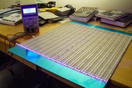
Just building a UV exposure unit for alternative printing. Should be able to get exposure times down to about 5-10 mins for Platinum Palladium and this unit will eventually have just under 16" by 20" exposure area. The UV LED strips are "5M UV 395nm 3528 SMD Purple 600 LED Strip Light Non-Waterproof 12V" £13.86 for 5m - 25m needed = £69.30. The LED driver is 12V 40A for £40. Sheet of aluminum and heatsink was £20 and I'll be building the vacuum mount which should be about £90 once finished. Total amount = about £250.

_DSC2429.jpg
 

Bob Carnie

Subscriber
Joined
Apr 18, 2004
Messages
7,735
Location
toronto
Format
Med. Format RF
I have a nice flatbed scanner and I have always thought exactly what you propose below would work for bringing
the film to the glass, the only glitch is that the neoprene would hinder the quality. But if one use an optically clear
material in place of the neoprene.. now we would be talking - I would love to see a picture for this contraption.

Its a lot like the enlarger vacumn easels I used which used the top film to suction down and make the contact.

Hi Bob,

That's just for an enlarger easel based vacuum table. For a contact print frame you need to make a vacuum sandwich to squeeze the glass, sensitized paper, film and some other layer (usually neoprene) together.

I'm going to try a 'loose' technique where I don't have an edge seal.

So basically I put my neoprene on the table
put the sensitized paper on top
put the film on top of that
place a thin tube connected to vacuum unit so it comes out near the paper
place a string from the tube around the edge of the paper (this allows the vaccum to travel all around the paper)
place the glass on top of this
turn on the vacuum

Tim
 

Bob Carnie

Subscriber
Joined
Apr 18, 2004
Messages
7,735
Location
toronto
Format
Med. Format RF
Great work Tim


Just building a UV exposure unit for alternative printing. Should be able to get exposure times down to about 5-10 mins for Platinum Palladium and this unit will eventually have just under 16" by 20" exposure area. The UV LED strips are "5M UV 395nm 3528 SMD Purple 600 LED Strip Light Non-Waterproof 12V" £13.86 for 5m - 25m needed = £69.30. The LED driver is 12V 40A for £40. Sheet of aluminum and heatsink was £20 and I'll be building the vacuum mount which should be about £90 once finished. Total amount = about £250.

View attachment 123792
 
Joined
Sep 7, 2002
Messages
629
Location
Sacramento
Format
Medium Format
Tim,

Before you install those LEDs on the plate, I would recommend a few things...

Depending on the LED product, you may not have any real light diffusion happening there, so I would recommend looking to see if the LEDs have an unusual 'beam pattern' to them. If they have a spikey pattern, you will need to keep them away from the print a decent amount so the patterns overlap and blend, and you may also want to consider staggering the rows so they do not line up into row-by-row pattern. Lastly, if they beam pattern is asymmetrical, you may want to think about rotating the strips to break up where the spikes are in the distribution.

If you use the general rule of 5x the distance from LED to LED as the absolute minimum for the distance to the print for uniformity, you should be OK, and this will act as a parallel plate condition (much like a film capacitor or an infinite dimension room). That is, it will be very even from the center to the edges, except for the last 1.2x to 2x of the gap distance from the LEDs to the print.

Turn on a strip, look at a single one shining on a piece of paper, and pull it back from the paper while you look for the beam. If it has a strong spike in a particular direction, you may want to pay attention to how this all goes together. If it has a strong center output and falls off gradually symmetrically, you are probably fine to install without paying attention to this.

No advanced degree here, by 25+ years in lighting and architectural engineering to back me up on this. Never hurts to think hard about what can go wrong to be sure that you cover the bases well.


---Michael
 

timparkin

Member
Joined
Sep 2, 2006
Messages
212
Format
35mm
Tim,

Before you install those LEDs on the plate, I would recommend a few things...

Depending on the LED product, you may not have any real light diffusion happening there, so I would recommend looking to see if the LEDs have an unusual 'beam pattern' to them. If they have a spikey pattern, you will need to keep them away from the print a decent amount so the patterns overlap and blend, and you may also want to consider staggering the rows so they do not line up into row-by-row pattern. Lastly, if they beam pattern is asymmetrical, you may want to think about rotating the strips to break up where the spikes are in the distribution.

If you use the general rule of 5x the distance from LED to LED as the absolute minimum for the distance to the print for uniformity, you should be OK, and this will act as a parallel plate condition (much like a film capacitor or an infinite dimension room). That is, it will be very even from the center to the edges, except for the last 1.2x to 2x of the gap distance from the LEDs to the print.

Turn on a strip, look at a single one shining on a piece of paper, and pull it back from the paper while you look for the beam. If it has a strong spike in a particular direction, you may want to pay attention to how this all goes together. If it has a strong center output and falls off gradually symmetrically, you are probably fine to install without paying attention to this.

No advanced degree here, by 25+ years in lighting and architectural engineering to back me up on this. Never hurts to think hard about what can go wrong to be sure that you cover the bases well.

Hi Micheal - I did my first tests on the UV box and the beam batter is pretty spread, probably 100 degrees. The first pt/pd test went very well with about 4x the maximum gap distance (approx 1.5 inch below the plane of LEDs)

The results looked very smooth but I'm still experimenting. I'll try to do a single LED test and publish it here for people to look at.

The really good news is that we got a 5 minutes exposure time to maximum black. even a 3 minute exposure time was acceptable and this was with what must have been a 5mm sheet of glass in a very chunky contact frame. More accurate tests to follow.

The Aluminum plate I used to mount the LEDs to got quite hot during operation so probably lifted from around 16C to 45C in the course of the 5 minute exposure. I'll be adding a heatsink and a small fan to it once it's in a box. I don't think this is necessary but it will probably help if I do back to back exposures.

Here's a few photos. I ran out of LED strips so I till be adding some more to make up the blue protected area at the sides of the block. Total exposure area will be 400x500mm so I reckon I can easily print an 16x12" image area regardless of sheet size. Probably enough for me to learn on :smile: Now to make the vacuum frame!

_DSC2507.jpg
_DSC2506.jpg
 

timparkin

Member
Joined
Sep 2, 2006
Messages
212
Format
35mm
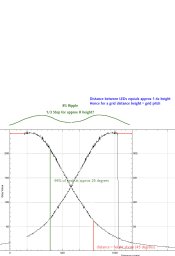
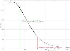
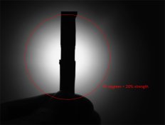
Single LED test done... I get a 95% of peak all the way out to 26 degrees (a spread of 50 degrees approximately).

At 45 degrees (90 spread) I get 20% of peak.

I've only checked visual spill but I imagine the drop off is the same for UV. I've included a photo and also two graphs. The interesting graph is the cumulative of two LED distributions separated by 1.414 (approx) hence for a grid this would be the diagonal (worst case scenario equals diagonal pitch).

The distribution for a single LED shows a pretty consistent beam at 25 degrees. At 45 degrees the intensity has dropped to 20%.

The graph where I show two curves is for two LEDs separated by 1.4x the height of the LED above the test plane. This shows a 1/3 of a stop ripple in intensity.

In other words I can get away with having the LEDs at a height of 1x pitch if I'm happy with a third of a stop ripple. For 2x pitch I think the ripple would be insignificant.

If you want to be absolutely certain I would make sure you're greater than 3x pitch and you can't go wrong..
 

Attachments

  • spread-cumulative.jpg
    spread-cumulative.jpg
    117.9 KB · Views: 209
  • spread-graph.jpg
    spread-graph.jpg
    71.6 KB · Views: 181
  • spread.jpg
    spread.jpg
    66.2 KB · Views: 189

Bob Carnie

Subscriber
Joined
Apr 18, 2004
Messages
7,735
Location
toronto
Format
Med. Format RF
Single LED test done... I get a 95% of peak all the way out to 26 degrees (a spread of 50 degrees approximately).

At 45 degrees (90 spread) I get 20% of peak.

I've only checked visual spill but I imagine the drop off is the same for UV. I've included a photo and also two graphs. The interesting graph is the cumulative of two LED distributions separated by 1.414 (approx) hence for a grid this would be the diagonal (worst case scenario equals diagonal pitch).

The distribution for a single LED shows a pretty consistent beam at 25 degrees. At 45 degrees the intensity has dropped to 20%.

The graph where I show two curves is for two LEDs separated by 1.4x the height of the LED above the test plane. This shows a 1/3 of a stop ripple in intensity.

In other words I can get away with having the LEDs at a height of 1x pitch if I'm happy with a third of a stop ripple. For 2x pitch I think the ripple would be insignificant.

If you want to be absolutely certain I would make sure you're greater than 3x pitch and you can't go wrong..


that's easy for you to say- Have you considered my question on whether it could work for silver prints as well as Pt Pd?
 

timparkin

Member
Joined
Sep 2, 2006
Messages
212
Format
35mm
that's easy for you to say- Have you considered my question on whether it could work for silver prints as well as Pt Pd?

I don't know but I would have thought so as it's kicking out a fair amount of visible light! I'll test it out if you're really interested?
 

Bob Carnie

Subscriber
Joined
Apr 18, 2004
Messages
7,735
Location
toronto
Format
Med. Format RF
I don't know but I would have thought so as it's kicking out a fair amount of visible light! I'll test it out if you're really interested?
I am interested Tim as Nuarc makes a very nice large LED vacumn plate burner around 6-7k $$ - it is for large prints the unit is very large.
I make 30 x40 silver digital negatives that are for contact process on silver and Pt Pd and it would be a great bonus to know this LED technology could work for both processes with the same unit.

I doubt their is a floor model I could use to see if it works for Pt Pd and Silver... Just knowing that it is possible allows more knowledge when talking with the sales agents who
will for sure not know what a silver print or a pt pd print is.

But I do not want to lead you down a path, I am not going to make a unit myself as I am not inclined like you ... I have 5 thumbs.
but if its not an issue for you I would love to understand how you would be able to adjust the Led for both wavelengths of light to maximize both process.
 

timparkin

Member
Joined
Sep 2, 2006
Messages
212
Format
35mm
I am interested Tim as Nuarc makes a very nice large LED vacumn plate burner around 6-7k $$ - it is for large prints the unit is very large.
I make 30 x40 silver digital negatives that are for contact process on silver and Pt Pd and it would be a great bonus to know this LED technology could work for both processes with the same unit.

I doubt their is a floor model I could use to see if it works for Pt Pd and Silver... Just knowing that it is possible allows more knowledge when talking with the sales agents who
will for sure not know what a silver print or a pt pd print is.

But I do not want to lead you down a path, I am not going to make a unit myself as I am not inclined like you ... I have 5 thumbs.
but if its not an issue for you I would love to understand how you would be able to adjust the Led for both wavelengths of light to maximize both process.

If you let me know what paper you want to use I'll buy some as I'm interested too.. The starfire (is that the nuarc one) looks amazing and isn't too badly priced if I had that sort of money. I'm hoping my full budget ends up less than $700 but with a reasonable amount of work involved. I will try to document it though and to be honest it really isn't that hard..

Tim
 

Bob Carnie

Subscriber
Joined
Apr 18, 2004
Messages
7,735
Location
toronto
Format
Med. Format RF
If you let me know what paper you want to use I'll buy some as I'm interested too.. The starfire (is that the nuarc one) looks amazing and isn't too badly priced if I had that sort of money. I'm hoping my full budget ends up less than $700 but with a reasonable amount of work involved. I will try to document it though and to be honest it really isn't that hard..

Tim
Ilford Warmtone or Bergger similar product - Yes that is the unit, problem will be that I will be coming in from left field(north american term ) and they probably not understand my request.

My thoughts are that they may be able to adjust the colour temp setting for different process being that this unit is LED at least that is what I am hoping. then it would be as simple as setting menus for Silver, Pt Pd , different gum colours, and of course any other process.
I have a line on some vacumn easels which could be used under an enlarger bulb filter setup if worse came to worse and the LED unit is only good for one process. This would take up more space but if required I would bite the bullet.

A couple of large projects and this unit could be paid for- so at this time I am looking for the best possible solution.

One thing about your set up is that if it works, the design could be biggie sized and a vacumn table could be made to slide under your unit.
 

timparkin

Member
Joined
Sep 2, 2006
Messages
212
Format
35mm
Ilford Warmtone or Bergger similar product - Yes that is the unit, problem will be that I will be coming in from left field(north american term ) and they probably not understand my request.
It would have not be variable contrast as the colour will be heavily blue balanced (or if it is VC then you'd have to live with and calibrate for maximum contrast)
My thoughts are that they may be able to adjust the colour temp setting for different process being that this unit is LED at least that is what I am hoping. then it would be as simple as setting menus for Silver, Pt Pd , different gum colours, and of course any other process.
I would bet a lot of money on the fact that the UV Leds can't be frequency tuned and they won't have visible light LEDs
I have a line on some vacuum easels which could be used under an enlarger bulb filter setup if worse came to worse and the LED unit is only good for one process. This would take up more space but if required I would bite the bullet.
Would these be enlarger vacuum easels or contact printing vacuum frames? (the former are no use for contact prints)
A couple of large projects and this unit could be paid for- so at this time I am looking for the best possible solution.
I'd love to find out how well they work! (and how much they actually cost, retail)
One thing about your set up is that if it works, the design could be biggie sized and a vacumn table could be made to slide under your unit.
Yes that was the plan. The unit can light only the image area and I can use a lot bigger paper/vacuum frame. I'm going to separate out the power supply from the LED platform so that I can use the power supply on a separate unit that has green LEDs on it (so I can use multigrade at low contrast). I might be better off with an enlarger for this but I'm not sure yet..

Tim
 
Joined
Sep 7, 2002
Messages
629
Location
Sacramento
Format
Medium Format
Single LED test done... I get a 95% of peak all the way out to 26 degrees (a spread of 50 degrees approximately).

At 45 degrees (90 spread) I get 20% of peak.

I've only checked visual spill but I imagine the drop off is the same for UV. I've included a photo and also two graphs. The interesting graph is the cumulative of two LED distributions separated by 1.414 (approx) hence for a grid this would be the diagonal (worst case scenario equals diagonal pitch).

The distribution for a single LED shows a pretty consistent beam at 25 degrees. At 45 degrees the intensity has dropped to 20%.

The graph where I show two curves is for two LEDs separated by 1.4x the height of the LED above the test plane. This shows a 1/3 of a stop ripple in intensity.

In other words I can get away with having the LEDs at a height of 1x pitch if I'm happy with a third of a stop ripple. For 2x pitch I think the ripple would be insignificant.

If you want to be absolutely certain I would make sure you're greater than 3x pitch and you can't go wrong..

Good to see that it is working well.

You may have already done it, but I am not sure I'd bother with a heatsink on this. I think I'd just get a small fan to move air across the back of the mounting plate. If you are going to have this in a cabinet, it will be a must, even with an heatsink.

Heat is the enemy of LEDs. It reduces their output, and their life. I'm sure you know that, but in this case, with so many packed together, it can be a problem for sure.

Also, I would not mount the two drivers anywhere near the mounting plate if you can help it. Mount them with a good gap between for air flow. Otherwise, you may have two regions that are different in output than the rest.


---Michael
 

timparkin

Member
Joined
Sep 2, 2006
Messages
212
Format
35mm
Good to see that it is working well.

You may have already done it, but I am not sure I'd bother with a heatsink on this. I think I'd just get a small fan to move air across the back of the mounting plate. If you are going to have this in a cabinet, it will be a must, even with an heatsink.

Heat is the enemy of LEDs. It reduces their output, and their life. I'm sure you know that, but in this case, with so many packed together, it can be a problem for sure.

Also, I would not mount the two drivers anywhere near the mounting plate if you can help it. Mount them with a good gap between for air flow. Otherwise, you may have two regions that are different in output than the rest.

Thanks Michael,

As I already have a heatsink I might put it on but I definitely don't "need" it. As you say, a few cheap, silent CPU fans will be used when it goes in a box. I'm also going to build a visible light version for normal contact printing and so I'm going to put the power supplies in a separate box with an IEC connector and a DC plug to swap them around. Good job as I never thought about the heat issue.

Out of interest, do you have a vacuum mount?
 
Joined
Sep 7, 2002
Messages
629
Location
Sacramento
Format
Medium Format
A vacuum frame?

I have an Amergraph ULF-28, which has one built in.

Previously, I had a Nuarc 40-1K, which also had one built in.

Before that, I had an Amergraph exposure unit just like a Nuarc 26-1K, which has one built in.

Before that... I had a fluorescent BL tube setup that I built, and it had a huge Teaneck vacuum frame that I purchased for it from a printer. All of these other then the current one I got used for pretty good prices, so I moved through them depending on my needs without thinking about it too much.

I also have a couple of printing frames that are spring loaded. Vacuum is much, much better, but you have to be careful to not put the print under too much of a vacuum, because you can squeeze solution that is deep inside the paper back up to the surface where it will instantly ruin your negatives!
 

timparkin

Member
Joined
Sep 2, 2006
Messages
212
Format
35mm
A vacuum frame?

I have an Amergraph ULF-28, which has one built in.

Previously, I had a Nuarc 40-1K, which also had one built in.

Before that, I had an Amergraph exposure unit just like a Nuarc 26-1K, which has one built in.

Before that... I had a fluorescent BL tube setup that I built, and it had a huge Teaneck vacuum frame that I purchased for it from a printer. All of these other then the current one I got used for pretty good prices, so I moved through them depending on my needs without thinking about it too much.

I also have a couple of printing frames that are spring loaded. Vacuum is much, much better, but you have to be careful to not put the print under too much of a vacuum, because you can squeeze solution that is deep inside the paper back up to the surface where it will instantly ruin your negatives!

I ask because I'm in the process of building my own and trying to figure out just how they work.

I have a sheet of 4mm rubber, a few sheets of silk screen material (which will have cut outs for various size prints) and I'm buying this vacuum pump.

http://www.ebay.co.uk/itm/261895127669?_trksid=p2055119.m1438.l2648&ssPageName=STRK:MEBIDX:IT

What I would like to have is the rubber at the bottom and the glass at the top but I'm interested in how most systems that work this way around seal the edges. I'm hoping that I can just use a strip of foam weather strip

http://www.ebay.co.uk/itm/2x5M-Foam...316055?hash=item33b05e8317:g:~DsAAOSwUV9WofzZ

I'll buy the vacuum pump and then test but would be interested in thoughts..
 
Joined
Sep 7, 2002
Messages
629
Location
Sacramento
Format
Medium Format
OK, sounds good.

Most of the rubber bladders that they use for vacuum frames have a seal gasket in the perimeter. I don't think foam weatherstripping will work too well for two reasons

1. It may be somewhat fragile.
2. It might be permeable to air in a way that will cause the frame to leak all the time.

Look at this site:

http://bostick-sullivan.invisionzone.com/index.php?/topic/708-homemade-vacuum-frame/

There is a cross-sectional drawing that shows the basic assembly of MOST frames That I have seen. Basically, the glass is on top, then the print materials, and then the bladder behind. The bladder is supported underneath, but it essentially "sucks up" to the glass when under vacuum. Note that the drawing has the frame inverted with the light at the bottom, whereas most printers print with the light at the top.

I would consider rubber tubing as they used in the linked discussion, or look into rubber gasket or weatherstripping material. It should hold up better and produce a good seal on the glass.

Definitely put a bleeder valve in the line so that you can control the amount of vacuum you put on the print.

I don't know about in the UK, but here contact exposure frames are pretty easily found if you live in a metro area, so I wouldn't be building one without doing a little google searching for a print shop frame first. I only say that because I'd rather spend my time printing than making stuff for the darkroom!

My current frame in the Amergraph is a piece of glass on a hinge on top (no frame). The bottom is the rubber bladder with the built-in seal ring on the perimeter. It lays on a metal bed and the vacuum pulls down on the glass some, and then the bladder pulls up tight on the glass once the seal around the perimeter is compressed.

It never fails to pull, even with the bleeder valve set to produce a vacuum that isn't a full vacuum.

I can post some photos if you need some.


---Michael
 

timparkin

Member
Joined
Sep 2, 2006
Messages
212
Format
35mm
OK, sounds good.

Most of the rubber bladders that they use for vacuum frames have a seal gasket in the perimeter. I don't think foam weatherstripping will work too well for two reasons

1. It may be somewhat fragile.
2. It might be permeable to air in a way that will cause the frame to leak all the time.

Look at this site:

http://bostick-sullivan.invisionzone.com/index.php?/topic/708-homemade-vacuum-frame/

There is a cross-sectional drawing that shows the basic assembly of MOST frames That I have seen. Basically, the glass is on top, then the print materials, and then the bladder behind. The bladder is supported underneath, but it essentially "sucks up" to the glass when under vacuum. Note that the drawing has the frame inverted with the light at the bottom, whereas most printers print with the light at the top.

I would consider rubber tubing as they used in the linked discussion, or look into rubber gasket or weatherstripping material. It should hold up better and produce a good seal on the glass.

Definitely put a bleeder valve in the line so that you can control the amount of vacuum you put on the print.

I don't know about in the UK, but here contact exposure frames are pretty easily found if you live in a metro area, so I wouldn't be building one without doing a little google searching for a print shop frame first. I only say that because I'd rather spend my time printing than making stuff for the darkroom!

My current frame in the Amergraph is a piece of glass on a hinge on top (no frame). The bottom is the rubber bladder with the built-in seal ring on the perimeter. It lays on a metal bed and the vacuum pulls down on the glass some, and then the bladder pulls up tight on the glass once the seal around the perimeter is compressed.

It never fails to pull, even with the bleeder valve set to produce a vacuum that isn't a full vacuum.

I can post some photos if you need some.


---Michael

That's fantastic Michael - a photo would be cool. I'll have a look for the bleeder valve and connectors..
 

Peabodius

Member
Joined
Feb 25, 2016
Messages
5
Location
Indiana
Format
4x5 Format
I ask because I'm in the process of building my own and trying to figure out just how they work.

I have a sheet of 4mm rubber, a few sheets of silk screen material (which will have cut outs for various size prints) and I'm buying this vacuum pump.

http://www.ebay.co.uk/itm/261895127669?_trksid=p2055119.m1438.l2648&ssPageName=STRK:MEBIDX:IT

What I would like to have is the rubber at the bottom and the glass at the top but I'm interested in how most systems that work this way around seal the edges. I'm hoping that I can just use a strip of foam weather strip

http://www.ebay.co.uk/itm/2x5M-Foam...316055?hash=item33b05e8317:g:~DsAAOSwUV9WofzZ

I'll buy the vacuum pump and then test but would be interested in thoughts..

How did you settle on that particular vacuum pump? I'm constructing a roughly 40"x50" vacuum frame, and I'm struggling to find any info on what pump would be appropriate.
 

timparkin

Member
Joined
Sep 2, 2006
Messages
212
Format
35mm
How did you settle on that particular vacuum pump? I'm constructing a roughly 40"x50" vacuum frame, and I'm struggling to find any info on what pump would be appropriate.
Information is in short supply and I can imagine you could use lots of different ones. However I decided to go a little up market to keep the noise down and chose a 2 stage pump instead of a 1 stage.


This is the one I'm going to use..

http://www.ebay.co.uk/itm/261895127669?_trksid=p2055119.m1438.l2649&ssPageName=STRK:MEBIDX:IT

Tim
 
Photrio.com contains affiliate links to products. We may receive a commission for purchases made through these links.
To read our full affiliate disclosure statement please click Here.

PHOTRIO PARTNERS EQUALLY FUNDING OUR COMMUNITY:


Ilford ADOX Freestyle Photographic Stearman Press Weldon Color Lab Blue Moon Camera & Machine
Top Bottom