Arduino AIO Darkroom Timer

Mansion

A
Mansion

  • 0
  • 0
  • 0
Lake

A
Lake

  • 0
  • 0
  • 0
One cloud, four windmills

D
One cloud, four windmills

  • 0
  • 0
  • 7
Priorities #2

D
Priorities #2

  • 0
  • 0
  • 6
Priorities

D
Priorities

  • 0
  • 0
  • 7

Forum statistics

Threads
199,015
Messages
2,784,647
Members
99,772
Latest member
samiams
Recent bookmarks
0

CocoMongo

Member
Joined
Jun 7, 2017
Messages
7
Location
Malaysia
Format
Medium Format
Hi this is literally my first post on Photrio but since I have been lurking here for so long and learnt so much, I figured I would publish my attempt on an Darkroom timer based on the F-stop system when used in conjuction with an enlarger.
First off before anyone thinks this is a super polished solution - it is not. It will be ridden with bugs and contain certain quarks - but it works for me. I am however more than happy to listen bug reports and suggestions including for new features.
However I did this project on my own very limited free time, so while bug reports are appreciated, do not expect corrections to be made within day or weeks. Lastly since this project involved mains powered electrical work - i.e. something that can kill you; be aware of the risks and if you are not confortable or competent doing electrical work... just don't.

And with that out of the way on to the good stuff.

Objective
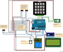
  • Create a cheap Arduino based darkroom timer that covers all time based activities and processes
  • Utilise “off-the-shelf” parts such as shields and breakout boards to eliminate custom PCBs and minimise individual component count
  • Define a standard hardware system which can be utilised by any one to create their own custom firmware and share for new "flavours"
  • Updatable and modular code structure that can be easily debugged/modified without impacting other functions of the code
  • Use of simple coding so any beginner C++/Arduino programmer can make changes (also an excuse due to my limited programming knowledge)
  • Maximise hardware so that there is (preferably and hopefully) one hardware version with different firmware flavour by other others by:
    • Effective use of pins i.e. using I2C for the LCD
    • Maximise pin use for inputs such as switches, keypad and rotary switch
    • A focus on UI/UX through larger screens (20x4 vs 16x2 LCD) so that users can be guided through the timer interface rather than reading the manual or having to remember all the steps/keys
  • As cheap as possible – so that we can buy more film!

Key Features/Functionalities
  • All in one timer for the darkroom with a focus on F-stop based calculator for the enlarger timer function.
  • Multiple input methods including a keypad, rotary dial with push button, dedicated button to enable enlarger focus and start/stop switch/foot switch.
  • Large 20x4 LCD to allow greater space for user interface design
  • Audio cue to allow users to focus on their activity (burn and dodge) while being aware of the time
  • Foot switch to allow hand free operations especially if hands are positioned for burning and dodging
  • Connections for mains powered safelight and enlargers up to 250v
  • Key software modes/function:
    • Clock and Countdown timer function
      • Minute/seconds clock – Simple timers with audio cue at the minute and second mark respectively
      • Countdown timer – User imputable countdown timer up to 999 minutes
    • Test strip creation function
      • User selectable method for test strip creation (gradually open or gradually close test strip)
      • User definable base time (shown in stops and seconds), number of exposure steps (up to 9), and exposure stops between first and last steps (in stops)
    • Enlarger timer
      • User definable method for print creation (Addition mode; building up on continuous exposure - i.e. user have pre-calculated the exposure differences in zones and are expecting to expose base only on the differences OR Absolute mode; knowing all the different exposure zone values and letting the system calculate the right for each zone
      • User definable exposure (in steps) up to 0.01 difference, burn (additive) or dodge (subtraction), dry down factor in percentage up to 1% difference, and filter factor (i.e. when filter factor 4 or more is defined, the timer will automatically add the defined filter factor to the exposure).
12 Jan 2020 - Uploaded timer documentation for version v1.1.0


P.S. Do watch this space as I am still putting the touchup to the documentation and polishing the Arduino Sketch and will put them up ASAP.
 

Attachments

  • DarkroomTimer_HWv1.x.x.jpg
    DarkroomTimer_HWv1.x.x.jpg
    635.9 KB · Views: 811
  • Darkroom Timer Documentation v1.1.0.pdf
    688.6 KB · Views: 2,373
Last edited:

MattKing

Moderator
Moderator
Joined
Apr 24, 2005
Messages
53,106
Location
Delta, BC Canada
Format
Medium Format
Welcome to posting on Photrio.
Your project is very interesting to me.
 
OP
OP

CocoMongo

Member
Joined
Jun 7, 2017
Messages
7
Location
Malaysia
Format
Medium Format
Documentation for the darkroom timer has now been uploaded. This document details as much as possible the reasoning and build of the timer - but also includes the formula used for some of the key functions. Any input on the formula and approah being implemented is appreciated. Will do a final check of the Arduino sketch tomorrow and have the final/key piece of the puzzle up by then.

Regards
 

radiant

Member
Joined
Aug 18, 2019
Messages
2,135
Location
Europe
Format
Hybrid
Welcome here, nice to have more DIYers around!

The documentation is quite impressive, really nice analysis and documentation!

I have also built myself an Arduino based darkroom timer which I use when printing. I used 3D printer display (128x64) for mine to get much data on the screen. The same technique I used on my darkroom light meter too.
 
OP
OP

CocoMongo

Member
Joined
Jun 7, 2017
Messages
7
Location
Malaysia
Format
Medium Format
Welcome here, nice to have more DIYers around!

The documentation is quite impressive, really nice analysis and documentation!

I have also built myself an Arduino based darkroom timer which I use when printing. I used 3D printer display (128x64) for mine to get much data on the screen. The same technique I used on my darkroom light meter too.

Thank you for your kind words. Documentation is always lacking in most DIY'ers and is something I am trying to overcome.
I would have really liked to use the similar type of screen you mentioned. Unfortunately when I started this built I was not yet aware of this style of screen. Maybe a potential V2 of the hardware in the future which will also means a huge rewrite of the Arduino sketch. Thanks for the input!
 

koraks

Moderator
Moderator
Joined
Nov 29, 2018
Messages
23,115
Location
Europe
Format
Multi Format
I used 3D printer display (128x64) for mine to get much data on the screen.
Moreover if memory serves you use a red back light lcd which is nice in a b&w darkroom. Lcd's can be further filtered by overlaying one or more layers of rubylith or another red foil material on top, which is something I usually do to get brightness down to appropriate levels for a darkroom.
 

radiant

Member
Joined
Aug 18, 2019
Messages
2,135
Location
Europe
Format
Hybrid
Moreover if memory serves you use a red back light lcd which is nice in a b&w darkroom. Lcd's can be further filtered by overlaying one or more layers of rubylith or another red foil material on top, which is something I usually do to get brightness down to appropriate levels for a darkroom.

I have covered the display with multiple layers of some ebay car light/window pimping red covering tape. Similar what is used to cover books but just in red. It dims the display and even if the light is not completely "red", it is so dim that it won't probably fog the paper at all.
 

koraks

Moderator
Moderator
Joined
Nov 29, 2018
Messages
23,115
Location
Europe
Format
Multi Format
Exactly, I do the same. Works quite well too for 7 segment led displays which have limited options for reducing light intensity electronically (at least the modules I've used so far).
 
OP
OP

CocoMongo

Member
Joined
Jun 7, 2017
Messages
7
Location
Malaysia
Format
Medium Format
Aww I was hoping I could have kept all the file releases on the first post until I found out that there is a time limit to edit post here on photrio. How unfortunate.

Anyhow complete v1.1.0 is released. I figured if I continued to make edits every day this is never going to be release so better do it now. There is only one external library that is required which can be downloaded at https://github.com/GreyGnome/PinChangeInt which is for the PinChangeInt.h file. As mentioned the coding is quite crappy but somehow works still. However anyone is welcome to have a go at it by reusing these codes or otherwise.
 

Attachments

  • DarkroomTimer_v1.1.0.zip
    631 KB · Views: 223
OP
OP

CocoMongo

Member
Joined
Jun 7, 2017
Messages
7
Location
Malaysia
Format
Medium Format

radiant

Member
Joined
Aug 18, 2019
Messages
2,135
Location
Europe
Format
Hybrid
I would really like to know how you implemented your F-stop enlarger timer logic for the entire print sequence. Could you share the logic?

My timer has maximum of four steps (so that they fit on one screen and I barely use more than 3). Each step is either burn or dodge operation and times are set in f-stops for each step. Dodge times subtract the burn times - keeping the total exposure identical to defined burn times.

The steps are calculated as increments in f-stops, so if I change the first burn f-stops the rest of the each step times change too because papers work that way :D
 
OP
OP

CocoMongo

Member
Joined
Jun 7, 2017
Messages
7
Location
Malaysia
Format
Medium Format
Opps I made a stupid mistake in the v1.1.0 initial release which drove the relays wrongly when in the Enlarger mode when executed. Version 1.1.1 corrects this plus some minor cosmetic fixes in Enlarger mode.

IMG_20200128_081422.jpg
These are the photos of the timer unit. Also yes I am pretty bad with the Dremel when cutting the holes - does not affect the image though :tongue:
This image shows the front; the 20x4 LCD screen, Focus Button (left side), Star/Stop switch (bottom of the keypad) and connected with the foot switch on the right, rotary encoder with puch button, and 4x4 keypad.

IMG_20200128_081456.jpg
Rear picture showing the Enlarger and Safelight power sockets connected to their individual relays internally and power in via a 10A 3pin IEC C13 power socket. Internally there is a 3A switching power suppy to provide the Arduino with regulated 5v power.
 

Attachments

  • DarkroomTimer_v1.1.1.zip
    557 KB · Views: 283
OP
OP

CocoMongo

Member
Joined
Jun 7, 2017
Messages
7
Location
Malaysia
Format
Medium Format
My timer has maximum of four steps (so that they fit on one screen and I barely use more than 3). Each step is either burn or dodge operation and times are set in f-stops for each step. Dodge times subtract the burn times - keeping the total exposure identical to defined burn times.

The steps are calculated as increments in f-stops, so if I change the first burn f-stops the rest of the each step times change too because papers work that way :D

Thanks for sharing!
We have the same implementation for the "Dodge time subtracting the burn times" but I have it under only one of the Enlarger modes (Addition if not mistaken). I am however hopeful i will get around programming the last major functions which will allow wholestock changes to the progamming especially useful when I want to say print from a 4x4" print to 8x8" print. Would you be ok I implement something similar to your function you have mentioned about how the first burn affects the rest of the enlarging sequence?
 

radiant

Member
Joined
Aug 18, 2019
Messages
2,135
Location
Europe
Format
Hybrid
Would you be ok I implement something similar to your function you have mentioned about how the first burn affects the rest of the enlarging sequence?

Of course it is OK. I don't know if it even counts as "idea" because there is no other way to do it - as far as I know.
 

alanbradford

Subscriber
Joined
Aug 30, 2010
Messages
214
Location
Switzerland
Format
Medium Format
Hi there CocoMongo,

This looks nice, do you have a reference for the 20x4 LCD Red on Black module please?

Thanks, Alan
 

alanbradford

Subscriber
Joined
Aug 30, 2010
Messages
214
Location
Switzerland
Format
Medium Format
Hi, CocoMongo, I get an error on upload of the sketch (v1.1.1) at this line, I am relatively new to Arduino so need some pointers here please

LiquidCrystal_I2C lcd(I2C_ADDR,En_pin,Rw_pin,Rs_pin,D4_pin,D5_pin,D6_pin,D7_pin);

no matching function for call to 'LiquidCrystal_I2C::LiquidCrystal_I2C(int, int, int, int, int, int, int, int)'

I tried both v1.1.1 and 1.1.2 of the Library - It does say this library may not be compatible with existing sketches - Maybe I have the wrong library?

Thanks, Alan
 

koraks

Moderator
Moderator
Joined
Nov 29, 2018
Messages
23,115
Location
Europe
Format
Multi Format
OP hasn't been seen for 2.5 years, so in case they might not respond, I'll try to help if you want.

I tried both v1.1.1 and 1.1.2 of the Library - It does say this library may not be compatible with existing sketches - Maybe I have the wrong library?

Yes, that's the most likely cause. I've checked and the LiquidCrystal_I2C that comes with the Uno should work with the following constructor:
LiquidCrystal_I2C lcd(0x27,20,4);
See if replacing line 56 with the one above helps to resolve the compile error.

If so, you'd also have to replace the following line (no. 186):
lcd.begin(20,4);
with:
lcd.init();

Also comment out line 88 ("lcd.setBacklightPin(BACKLIGHT_PIN,POSITIVE);")

No guarantees that covers all of it, though; I've only done a cursory check. To be sure: that's 3 modifications listed above that you'll likely need to perform to get the thing to compile. I tried compiling it for an Arduino UNO and get no errors after performing these modifications. I used the Keypad library by Stanley & Brevig, version 3.1.1

Please note that when troubleshooting Arduino issues online, the following information usually vital:
* A schematic of the circuit as you've built it
* Details of components used; e.g. in this case the exact type of LCD module can be relevant to know. Also relevant is the exact Arduino (or Arduino clone) you're working with
* The version of the Arduino IDE you're using and any libraries installed, as well as a specification of which platform you're compiling the code for (i.e. what you select under Tools -> Board)
* The code as you're compiling it. In this case I assumed you are working with the modified code as posted by OP, but once you progress in modifying it, it becomes vital to share the code you're actually working with

When running into issues like yours, the best strategy is to create a minimum demonstrator of the problem. I.e. in this case, you could create a new project that just starts the LCD and puts a message on it. In this case, it's actually already handed to you ready-made; in the Arduino IDE, see File -> Examples. In this (large) foldout menu you should find some examples specifically for the I2C LCD library that you have installed.

Btw, to be frank, I think I would have programmed the core program logic a little differently than it's done now. It's a bit of a hodgepodge of approaches and overall would have been far more transparent if it had exploited the obvious combination of an object-oriented approach and a proper finite state machine. In its present state, it's not very intuitive to debug.
 
Last edited:

koraks

Moderator
Moderator
Joined
Nov 29, 2018
Messages
23,115
Location
Europe
Format
Multi Format
do you have a reference for the 20x4 LCD Red on Black module please?

Just to add my 2cts to this one: I've also searched for a bit for something like this, but 20x4 is a bit less common than 16x2 to begin with, and we tend to get them in only a few default color schemes. For my enlarger controller I ended up picking any old black-text-on-white-background 20x4 LCD and modify it with a custom backlight. It turns out that the backlight is generally one or two blue or white LEDs that shine into the narrow sides of the LCD itself. Replace these with any color you like, or even RGB LEDs. If you want to go fancy, you can even add a little pwm module (just a small signal mosfet and two resistors, basically) to make the backlight dimmable from one of the Arduino's pwm pins.
 

alanbradford

Subscriber
Joined
Aug 30, 2010
Messages
214
Location
Switzerland
Format
Medium Format
Thank you so much Koraks!
I am using the same Stanley and Brevig v3.1.1 keypad as you and an Arduino UNO (clone) which has worked fine on other sketches.

I followed step by step what you gave me and all now compiles without errors - I have not got the Timer built as I am waiting for parts, but the 20x4 LCD I found was not Red but I needed a smaller one anyway, so found this for good price - https://www.buydisplay.com/small-size-blue-lcd-bezel-20x4-arduino-library-character-display-module and will cover it in Rubylith.

I'll update this later once I have the Timer built, but thanks again for such a rapid and great help. Alan
 

koraks

Moderator
Moderator
Joined
Nov 29, 2018
Messages
23,115
Location
Europe
Format
Multi Format
Brilliant! Good to hear. Feel free to update / reach out if you run into anything.

Your display module looks fine, but you may need a few layers of Rubylith to make it B&W safe. Just experiment and see! Did you make sure to order the I2C backpack to go along with it?
 

alanbradford

Subscriber
Joined
Aug 30, 2010
Messages
214
Location
Switzerland
Format
Medium Format
Yes, I did indeed add the I2C backpack. Thanks for looking out for me, it's really great when experienced people take the time to help the beginners..
 
Photrio.com contains affiliate links to products. We may receive a commission for purchases made through these links.
To read our full affiliate disclosure statement please click Here.

PHOTRIO PARTNERS EQUALLY FUNDING OUR COMMUNITY:


Ilford ADOX Freestyle Photographic Stearman Press Weldon Color Lab Blue Moon Camera & Machine
Top Bottom