Niglyn
Member
I see, and for the receivers I just use the diode part of the ky007 module? Or is there a part number for only the diode?
Hi, the sensors are not available separately, only as part of the module.


I see, and for the receivers I just use the diode part of the ky007 module? Or is there a part number for only the diode?
Hi,
At last I have started again the project after recovering from a broken vertebrae.
I am 3d printing everything
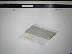
Maybe this question came along but the bottom part of the laser setup seems to be to big for the building plate. I am using a 220×220mm building plate commonly under 3d printers.
When I scale to 99,3% it fits so it is just 1 mm to big ! How did you solve his? Scaling X axis to 99,3 or modifying in the settings of the printer the building plate settings?
Hi, when you look at the sensors, not only do they have the lens that protrudes, but also a rectangular protrusion.
It is the rectangular protrusion that stops the lens fitting in a hole. Otherwise, the pcb could have the holes drilled for the lens to look through. The sensor could then be easily mounted on the component side of the pcb and look though the hole on the pcb.
The 3d printed enclosure has a recess for the rectangular protrusion and hole for the lens. A cap then goes on the back, to hold it in place.
So, to make a pcb and get all five sensors correctly aligned would be nightmare.
However, as I type this, a genius idea has just popped into my brain, of a simple way to achieve this.
Simple is relative, I would have to spend time designing the pcb and associated 3d printed parts and I am not sure many people would want the added expense of ordering pcbs.
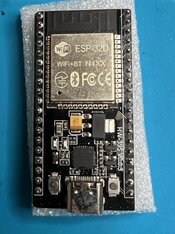
Thank you. My parts arrived today - just checking on the ESP-32 that I was sent - it's an ESP-32D - photo attached. I ordered the CP2102 version - but there is no marking on the chip, so not sure what it is. IT was the link in parts from a builder who said it worked. Will this be ok and work with your software?
Hi, yes that is perfect.
It will undoubtedly be the 2102 USB driver. Even if it is not, it is no great issue. Windows Device Manager will show which driver it is & if your computer has it loaded.
Thank you. I hope to start putting it together this weekend (sans 3D parts) - at least the control part. To get the code, I don't need to build all the sensor component - just the TFT, ESP, switches and rotary encoder?
Hi, I have never thought about build plate sizes.
Designed it using my machne & that is about all I can do.
Different manufactures & machines will have different tollerances and quirks.
Mine, for example will always print holes smaller than drawn. I would have thought the post-processor should adjust, to ensure the drawn and printed size is the same, mine does not.
Have just checked the drawing, by coincidence the length is 220mm.
Easy enough to lop off the ends, will do this now. Should be on Github later today.
View attachment 425703

Hi, just the rotary encoder and blue button connected will get you going.
Output can be viewed on the pc screen (using Arduino Serial monitor, or any comms terminal program) so even if the tft is mis-wired or having issues, one can see ifthe esp32 is working ok.
Although, please try not to mis-wire the tft. It has delicate electronics and mis-wiring could easily damage it.
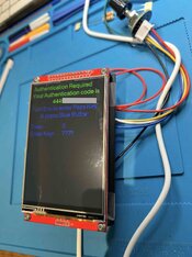
Hi, so I sent a message to request an authorisation code.
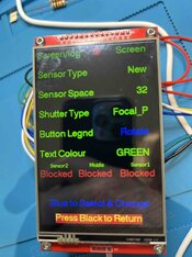
My TFT is a white background and not black - have I done something wrong? Very hard to see the yellow writing.
I checked the wiring several times, and it appears to be correct.
Please let me know.
Regards
Hi, so I sent a message to request an authorisation code.
My TFT is a white background and not black - have I done something wrong? Very hard to see the yellow writing.
I checked the wiring several times, and it appears to be correct.
Please let me know.
Regards
Hi, I have put a new file for you on github. In the firmware folder, there is a folder called bm282
use the firmware.bin file in this folder, to replace the original and re-flash your esp32.
Please post some photos of the screen to show if the colour has changed.
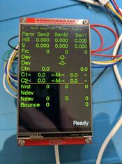
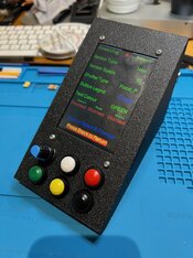
So progress - have finished putting the control unit together. Next is to start on the sensors and lasers setup... Such a great system...
 )()
)()Hi, looking good so far
Aliexpress is normally ok, but one does have to check the quality of the items. Some are worthless junk, but there are also great bargains and prices for the same item, if bought locally, are often much cheaper. Was even better before the tax man cottoned on. We now have to pay tax at 20% on all purchased items
The sellers use a model similar to Amzon, where stock is held centrally and often mixed with other sellers with the same item.
So it is often difficult or impossible to get any more detail than available on their listing and if there are changes by the manufacturer, these are often not updated on the seller's listing.
The mix-up with the expansion boards is a case in point. With a listing showing the correct board, but gets substituted with the board with the wider pin spacing.
In the production world, one would never use parts from Aliexpress. Whilst it might be the same part but at a higher price, listed on Farnell etc, there is a better chain of purchase, with any changes noted.
I have no idea why your screen is white. It has been seen on two 3.5" screens, but not, to my knowledge on a 4" screen.
If it is a fault with the tft or driver chip, or the chip/display is a different variant and the manufacturers used them anyway, I have no idea, but would love to know.
Your code is bespoke, but I will have to see if the code for any future updates can be adjusted to cater for inverse screens.
Happy building

Hi, looking good so far
Aliexpress is normally ok, but one does have to check the quality of the items. Some are worthless junk, but there are also great bargains and prices for the same item, if bought locally, are often much cheaper. Was even better before the tax man cottoned on. We now have to pay tax at 20% on all purchased items
The sellers use a model similar to Amzon, where stock is held centrally and often mixed with other sellers with the same item.
So it is often difficult or impossible to get any more detail than available on their listing and if there are changes by the manufacturer, these are often not updated on the seller's listing.
The mix-up with the expansion boards is a case in point. With a listing showing the correct board, but gets substituted with the board with the wider pin spacing.
In the production world, one would never use parts from Aliexpress. Whilst it might be the same part but at a higher price, listed on Farnell etc, there is a better chain of purchase, with any changes noted.
I have no idea why your screen is white. It has been seen on two 3.5" screens, but not, to my knowledge on a 4" screen.
If it is a fault with the tft or driver chip, or the chip/display is a different variant and the manufacturers used them anyway, I have no idea, but would love to know.
Your code is bespoke, but I will have to see if the code for any future updates can be adjusted to cater for inverse screens.
Happy building
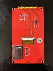
Further to the issue of the IPS, I am advised that the YMKJ Store is via the Aliexpress warehouse for the product. The warehouse can pick the wrong item and send an IPS version instead of a TFT version of the display.
To order the TFT version directly from the supplier and not via Aliexpress warehouse, they said to use the link below. IF you want touch, order the RTP version.
Hope this helps folk.
Regards

 newhavendisplay.com
Hi, thanks for the info.
IPS is still a tft technology and has some benefits & disadvantages over regular tft.
One being price, IPS being more expensive. What is the bet most screens on Aliexpress having IPS in the title are regular tft?
Read all about it here.
TFT vs IPS: Is There a Difference?
Explore the difference between TFT vs IPS displays. Newhaven Display explains key features, advantages, and use cases for your designs.
Below, is the standard configuration used for the tft display and is embedded within The Shutter Tester firmware.
It is not flashed to or held separately on the tft. The configuration does not remain on the tft after power-off.
It is obviously not possible to make changes to individual bit settings on an ad-hoc basis.
// Configure ILI9488 display
writecommand(0xE0);
writedata(0x00);
writedata(0x03);
writedata(0x09);
writedata(0x08);
writedata(0x16);
writedata(0x0A);
writedata(0x3F);
writedata(0x78);
writedata(0x4C);
writedata(0x09);
writedata(0x0A);
writedata(0x08);
writedata(0x16);
writedata(0x1A);
writedata(0x0F);
writecommand(0XE1);
writedata(0x00);
writedata(0x16);
writedata(0x19);
writedata(0x03);
writedata(0x0F);
writedata(0x05);
writedata(0x32);
writedata(0x45);
writedata(0x46);
writedata(0x04);
writedata(0x0E);
writedata(0x0D);
writedata(0x35);
writedata(0x37);
writedata(0x0F);
writecommand(0XC0);
writedata(0x17);
writedata(0x15);
writecommand(0xC1);
writedata(0x41);
writecommand(0xC5);
writedata(0x00);
writedata(0x12);
writedata(0x80);
writecommand(TFT_MADCTL);
writedata(0x48);
writecommand(0x3A);
writedata(0x66);
writecommand(0xB0);
writedata(0x00);
writecommand(0xB1);
writedata(0xA0);
writecommand(0xB4);
writedata(0x02);
writecommand(0xB6);
writedata(0x02);
writedata(0x02);
writedata(0x3B);
writecommand(0xB7);
writedata(0xC6);
writecommand(0xF7);
writedata(0xA9);
writedata(0x51);
writedata(0x2C);
writedata(0x82);
writecommand(TFT_SLPOUT);
delay(120);
writecommand(TFT_DISPON);
// End of ILI9488 display configuration
| Photrio.com contains affiliate links to products. We may receive a commission for purchases made through these links. To read our full affiliate disclosure statement please click Here. |
PHOTRIO PARTNERS EQUALLY FUNDING OUR COMMUNITY:  |