RH Design Analyser 500 for Ilford MG 500 system

Forum statistics

Threads
198,308
Messages
2,772,695
Members
99,593
Latest member
StephenWu
Recent bookmarks
1

Marco B

Subscriber
Joined
Jan 13, 2005
Messages
2,731
Location
The Netherla
Format
Multi Format
Hi all,

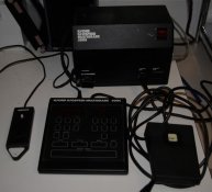
Grrr... it seems my Ilford 500C control unit is toast :sad:

Recently, I noticed some malfunction, sometimes the unit wouldn't properly start up. This deteriorated fast, with the enlarger head's lights no longer switching off and the system going haywire. Since handling the cable from the 500C control unit seemed to aggravate the problems, I initially thought I had a simple cable issue. But now, after a lot of work and replacing the cable connecting the control unit with the transformer / power unit, requiring the soldering of an 8 core wire, it still malfunctions. It is now fully disfunctional, only giving a permanent beep and displaying nonsense in the LED display.

So, while I still suspect a cable short-cut due to cable flexing and ageing is the primary cause of the issues, I do think some other part of the control unit went bust in the process...

I am now possibly considering buying one of these RH Design Analyser 500 control units as a possible replacement. However, I have a few questions about this:

- What are your experiences with this control unit on the Ilford Multigrade 500 system?

- Can it be used exactly as with the Ilford 500C unit, e.g. by simply setting time and grade? Up to now, I have never used the "probes" that came with my Ilford system, but it seems the Analyser 500 may require it? Or can you simply use it as the 500C unit, with the probe as an "optional" feature, as I would prefer...

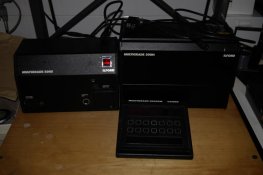
In addition, I am still hoping it's only the 500C unit gone bust, because, out of curiosity, I also opened up the Ilford 500S power unit / transformer. I noticed there is actually a bit more electronics there than I had expected, including at least one IC (integrated circuit) unit. I hope nothing else went toast in the process, because in that case buying the RH Design Analyser 500 might be a waste of money...

I also noticed RH Design doesn't build these kind of power units? What do you do when the Ilford 500S unit breaks down? Besides getting a second hand one, are there any possible modern new replacements? And what about the Analyser 500 unit if the Ilford 500S also fails, am I right to assume I need to get both a new power unit AND a new control unit, since the RH Design Analyser 500 only works in combination with the Ilford 500S?

A lot of questions, hope at least some can be answered by you all.

Thanks,

Marco
 
Last edited by a moderator:

L Gebhardt

Member
Joined
Jun 27, 2003
Messages
2,363
Location
NH
Format
Large Format
I have the Analyser 500 and it can work similar to the original 500C. The differences I have noticed are: 1) grades no setable in .1 increments instead of .5; 2) First the green, then the blue portion of the exposure is done as opposed to both lamps together.

This allows much more control and also dodging or burning with hard or soft light.

If this is the only features you want RH designs makes an fstop timer for the 500 system (without the analyser). I haven't used this, but I think it works like the analyzer if you don't take any readings.

If you take the time calibrate the Analyser to probe works amazingly well. The grades are dead on, and the exposure readings are almost perfect. For the most part I don't need to make test strips anymore, just test prints. Thought the system does have nice facilities for fstop based test strips as well.

As far as fixing the 500S unit, it is something I have been wondering about as well. I would love to pickup a spare. Maybe RH Designs knows how to rebuild these. They seem to be wizards with electronics.

If you want to pay for shipping both ways I could loan you my 500C control unit to test your unit out with. I'm in the US, so shipping may not be cheap.
 

mattk

Subscriber
Joined
Mar 26, 2006
Messages
283
Location
Minnesota, U
Format
Medium Format
I picked up a Iford 500 Head on a D2 and it was real problematic. It would cut out and not start up or just not start at all. I suspected a short in the cable. I opened up the terminal end of the cable that plugs into the power supply and sure enough there was a short. The cables were soldered in an akward way so I redid the whole thing and try not to flex it. Works fine. You might give it a look--at the very least smell the plug and see if it smells burnt.
 
OP
OP
Marco B

Marco B

Subscriber
Joined
Jan 13, 2005
Messages
2,731
Location
The Netherla
Format
Multi Format
so I redid the whole thing and try not to flex it. Works fine. You might give it a look--at the very least smell the plug and see if it smells burnt.

I already did that, I replaced the cable and soldered in the 8 wires new... not that I consider my soldering work any better than that of Ilford, far from it, but there was no short in the plug part of the cable to begin with, and I double checked it after my own "repair" :rolleyes: ...

I am pretty sure there is no short now... well, at least not in the replaced cable. Of course, if any other part is toast as it seems to be, it is probably short circuiting.
 
Last edited by a moderator:

Fintan

Member
Joined
Jan 29, 2004
Messages
1,795
Location
Ireland
Format
Multi Format
I have the RH Designs Stop Clock 500 and I love it, its one of the best things I ever bought, even though there was nothing wrong with my ilford control unit
 

Pete H

Member
Joined
Oct 25, 2004
Messages
771
Location
Stavanger or
Format
Multi Format
Marco,

My Multigrade 500 head can be temperamental. Sometimes it starts counting down in steps of 10 seconds, and cycles round when it reaches 0 back to 90. When it does that it is impossible to set anything or use it - I usually switch it off for a while. I phoned the people at Lightwave in the UK (where I bought it - used) and they said that can happen if the mains supply voltage fluctuates too much. I've noticed that it is worse if the oven or washing machine is on in the house, so it seems to be plausible. I certainly have less problems printing during the day and late at night than I do in the early evening when people are cooking, washing, etc.

So I'm looking for a spare power supply too - just in case it fails completely.

I don't know if this helps - it sounds as though your problem is worse. It's a shame as they're great to use.

Pete
 

paul ewins

Member
Joined
Jan 5, 2006
Messages
446
Location
Melbourne, A
Format
4x5 Format
I recently bought a second MG 500 set up to use as spares. It was when I got it home that I discovered that there are two versions and they aren't compatible! The early version has the 500C, 500S and 500H (as well as the probe and footswitch). The later version has a 500CPM controller with 500S and 500H. Not only that, the socket on the 500S that you connect to the 500H has a different pin (extra long round pin) so that you can't plug a new head into the old power supply and probably vice versa. The new 500S has some short of short as it trips the circuit breakers as soon as it is plugged into a power outlet, whether or not it is turned on. I had hoped that I could just keep the rest as spares but I have ended up with two separate systems. I'm hoping the 500S fault is trivial as I couldn't see any burning inside.

In the attached photos the first two are the early version.
 

Attachments

  • early 500H.jpg
    early 500H.jpg
    57.3 KB · Views: 196
  • 500C.jpg
    500C.jpg
    71.7 KB · Views: 231
  • 500CPM.jpg
    500CPM.jpg
    53.9 KB · Views: 187

Andrew4x5

Member
Joined
Mar 9, 2007
Messages
56
Location
Australia
Format
4x5 Format
The Analyser 500 is a great device, especially if you spend time calibrating it. It directly replaces the Ilford control unit - you simply unplug the Ilford control unit and plug in the Analyser 500.

However, as you noted, Analyser 500 can only be used with the Ilford 500 head and power supply.

So, if the power supply (or head) fails, you have a problem. And, as Paul found out, there are at least two variants of the 500 system, with various levels of compatibility. Which rather complicates the search for spare parts.

Regarding repairing your controller if you know a bit about electronics (or know someone who does) you can download the service manual from http://www.ilfordphoto.com/products/page.asp?n=161. (This is for the last of the variants, with serial numbers 5H5xxx, 5S5xxx, etc.)
 
OP
OP
Marco B

Marco B

Subscriber
Joined
Jan 13, 2005
Messages
2,731
Location
The Netherla
Format
Multi Format
My Multigrade 500 head can be temperamental. Sometimes it starts counting down in steps of 10 seconds, and cycles round when it reaches 0 back to 90. When it does that it is impossible to set anything or use it - I usually switch it off for a while. I phoned the people at Lightwave in the UK (where I bought it - used) and they said that can happen if the mains supply voltage fluctuates too much....

I don't know if this helps - it sounds as though your problem is worse. It's a shame as they're great to use.

Pete, my problem is worse... it used to work perfectly.

I don't think there is a major issue with the supply voltage. Although any device in your house can cause (temporary) fluctuations when in use, the overall reliability of the Dutch grid is very high with only very rare outages. Besides the main high voltage powerlines, all other powerlines, whether in city or countryside, are below ground.

And I have even used the device with a washing machine running in my house, never had an issue with that.
 
OP
OP
Marco B

Marco B

Subscriber
Joined
Jan 13, 2005
Messages
2,731
Location
The Netherla
Format
Multi Format
The Analyser 500 is a great device, especially if you spend time calibrating it. It directly replaces the Ilford control unit - you simply unplug the Ilford control unit and plug in the Analyser 500.

Good to hear all the positive comments regarding the use of the RH Design replacement control units, so that will be a viable option. Thanks all!

Regarding repairing your controller if you know a bit about electronics (or know someone who does) you can download the service manual from http://www.ilfordphoto.com/products/page.asp?n=161. (This is for the last of the variants, with serial numbers 5H5xxx, 5S5xxx, etc.)

I already noticed that via another thread. I will have a look if I can find someone that might be able to check the device. With luck, the thing is still repairable, but I don't have the advanced electronic skills or experience to measure all the components reliably.

Replacing that cable was about all I could seriously do... and I didn't see any obvious faults like popped condensators, which would be a good clue to an issue.
 
OP
OP
Marco B

Marco B

Subscriber
Joined
Jan 13, 2005
Messages
2,731
Location
The Netherla
Format
Multi Format
The early version has the 500C, 500S and 500H (as well as the probe and footswitch). The later version has a 500CPM controller with 500S and 500H. Not only that, the socket on the 500S that you connect to the 500H has a different pin (extra long round pin) so that you can't plug a new head into the old power supply and probably vice versa.

Mine is the earlier version, with the 500C control unit.

For anyone reading this, please note, there is also another variation of the Ilford 500 Multigrade head: early devices only supported 150W lamps, while later ones supported 300W but had a crucial modification in the form of added metal heat baffle plates. I have written about that in another recent thread, see that one for more info and some scans of the Ilford manual explaining it:

(there was a url link here which no longer exists)

Marco
 

keeds

Member
Joined
Sep 26, 2005
Messages
361
Location
Suffolk, Eng
Format
Multi Format
My 500S power supply went pfftt a while back. I managed to get it repaired but it cost a pretty fortune. Odyssey Sales did the repair, but it took a while as they did not have parts. I have since managed to get a second hand 500S as backup. I use a RH Designs Stopclock Pro and it's great. I may have a spare 500 controller if you are after a replacement.
 
OP
OP
Marco B

Marco B

Subscriber
Joined
Jan 13, 2005
Messages
2,731
Location
The Netherla
Format
Multi Format
I use a RH Designs Stopclock Pro and it's great. I may have a spare 500 controller if you are after a replacement.

Thanks, I will definitely keep this in mind and if the controller turns out to be unrepairable, I will likely contact you.
 

marcos

Member
Joined
Jul 11, 2006
Messages
17
Location
Santander, S
Format
Medium Format
I´m having the same problem with my power supply.
I have the 500S and 500 CPM, and even recently bought the stop clock 500 by RH Designs.
Does anyone know if the Stopclock 500 uses the variable voltages to the lamps from the power supply?
If it is it "fixed voltage and variable filter times" the stopclock could be used with a simple transformer...
Anyway, if anyone finds the way to get a new 500s power supply I would like to know.
 

RH Designs

Advertiser
Advertiser
Joined
Apr 9, 2003
Messages
651
Location
Yorkshire Da
Format
Multi Format
Both Analyser 500 and StopClock 500 use full power and vary the time ratio, as per "split grade printing". I guess you could use a standard transformer but you'd also need to rig up something to control the cooling fan(s) and safelight as well as to provide the 12v DC the Analyser/StopClock require.
 

marcos

Member
Joined
Jul 11, 2006
Messages
17
Location
Santander, S
Format
Medium Format
Thanks for your answer Richard.
I suppose an important part is a voltage stabilization device, in order to avoid large variations in mains voltage or interference on the mains supply and be able to get repeatable results.
marcos.
 

RH Designs

Advertiser
Advertiser
Joined
Apr 9, 2003
Messages
651
Location
Yorkshire Da
Format
Multi Format
The controller has its own voltage regulator for the electronics; I don't know whether there is any compensation for voltage variations built into the lamp drivers in the power supply.
 

Andrew4x5

Member
Joined
Mar 9, 2007
Messages
56
Location
Australia
Format
4x5 Format
Regarding voltage regulation: On the CPM controller there is a VC switch. According to the Ilford Operating Manual, this switch enables/disables the power supply's inbuilt voltage control mechanism. (The manual says to disable the voltage control mechanism only if you connect the power supply to an external voltage control device.)

Given that the Analyser 500 replaces the CPM controller, I'm not sure whether the power supply's inbuilt voltage control mechanism is enabled or disabled - I would hope that it's enabled. Perhaps Richard knows what the answer is.
 

Marc Nocart

Member
Joined
Jun 24, 2008
Messages
2
Format
Med. Format Pan
Hi All,
Re. the regulation, I had a look to diagram and it seems to me - but I may be wrong - that the voltage stabilisation does not apply to the lamp, but rather on the remaining functions (timer and grade programmation). Which is quite surprising, I admit.

Basically as the lamps are 115V, you'll see that they are powered directly from the secondary of the transformer, through thyristors that are just used as a sort of tap to modulate the power send to each lamp (the ratio between these powers driving then the resulting contrast, achieved here in one exposure), which is managed the by the console.


For those who experienced troubles in the ignition of the lamps,
the thing is to determine whether the problem comes from the control unit or from the power unit. Irregular switching of the lamps often come from the ageing relays located within the power unit that does not hold their position when instructed by the console.

I had once no switching of the green but got the blue lamp (I had alreday plugged the analyser 500). When I tapped the unit on the right side, then sometimes I got the green switching on. Just changing the relays solved the matter.

Good luck
 
OP
OP
Marco B

Marco B

Subscriber
Joined
Jan 13, 2005
Messages
2,731
Location
The Netherla
Format
Multi Format
Hi all,

I thought I let you all know the current state of affairs.

I have come in contact with another Dutch APUG member (Theo) who knows an awful lot of electronics. He has helped me to interpret the component layouts and circuit diagrams of the Ilford 500 system as available here:

http://www.ilfordphoto.com/products/page.asp?n=161

We have mainly concentrated on the power supply, since this is the easiest component and the first in the chain, and the most vital one, since the controller is replaceable with the RH design ones.

We've managed to verify it's health, targeting different components and measuring voltages etc...

In addition, after some good interpretive help of Theo, I managed to switch the power supply using some paper-clips in the controller socket on the power supply, connected to a 1.2 V battery. There was LIGHT! Quite cool actually, to be able to manually switch these lights based on some excellent electronics knowledge by Theo. This means the power supply is almost certainly OK.

The bad news: after resoldering the cable a second time in much better way, I am now almost certain the controller is fried, and needs replacement. It will be hard if impossible to repair it, or at least much more difficult to find the error, since the unit is far more complicated than the power supply.

Marco
 
Last edited by a moderator:

L Gebhardt

Member
Joined
Jun 27, 2003
Messages
2,363
Location
NH
Format
Large Format
The bad news: after resoldering the cable a second time in much better way, I am now almost certain the controller is fried, and needs replacement. It will be hard if impossible to repair it, or at least much more difficult to find the error, since the unit is far more complicated than the power supply.

Maybe that's actually good news. You can replace the controller with a much better RH Designs one, or maybe convince one of us who has already done that to part with our old one.
 
OP
OP
Marco B

Marco B

Subscriber
Joined
Jan 13, 2005
Messages
2,731
Location
The Netherla
Format
Multi Format
The unit is repaired! :smile:

You can read the whole story in my last post in this thread:

(there was a url link here which no longer exists)

Many thanks to Theo van Kints, a fellow Dutch member of APUG to help me out.

Marco
 
Photrio.com contains affiliate links to products. We may receive a commission for purchases made through these links.
To read our full affiliate disclosure statement please click Here.

PHOTRIO PARTNERS EQUALLY FUNDING OUR COMMUNITY:


Ilford ADOX Freestyle Photographic Stearman Press Weldon Color Lab Blue Moon Camera & Machine
Top Bottom