Printed Circuit Boards made in the Darkroom?

Dog Opposites

A
Dog Opposites

  • 2
  • 3
  • 107
Acrobatics in the Vondelpark

A
Acrobatics in the Vondelpark

  • 6
  • 4
  • 186
Finn Slough Fishing Net

A
Finn Slough Fishing Net

  • 1
  • 0
  • 104
Dried roses

A
Dried roses

  • 13
  • 7
  • 193
Hot Rod

A
Hot Rod

  • 5
  • 0
  • 117

Recent Classifieds

Forum statistics

Threads
197,468
Messages
2,759,531
Members
99,512
Latest member
vincent83
Recent bookmarks
0

wombat2go

Member
Joined
Jul 21, 2013
Messages
352
Location
Michigan
Format
Medium Format
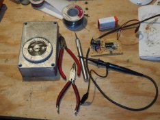
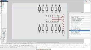
I am about to make a printed circuit board, actually it is to restore an old light meter.

I know there are modern methods and internet services probably easier and less cost,
but I thought I would like do it like 30+ years ago.

The elementary way back then was photoresist applied by brush to copper boards, then exposed under the sun
with the hand crafted artwork negative located with pins and held in a vacuum box.
- I forget all the details but it involved a trip to the (as I recall, reluctant) local photo shop for a negative.

Has anybody here done this in the darkroom, perhaps with an ordinary camera and b/w enlarger directly onto the copper?

Thanks
 

Jim Jones

Subscriber
Joined
Jan 16, 2006
Messages
3,745
Location
Chillicothe MO
Format
Multi Format
Long ago I made one with litho or Tech Pan film and sunlight. A contact printing frame held everything together, although such a frame can easily be improvised. An enlarger wouldn't provide a practical amount of light. A suntan lamp might do the job.
 

ic-racer

Member
Joined
Feb 25, 2007
Messages
16,483
Location
USA
Format
Multi Format
I don't use my darkroom at all. Photocopy the pattern onto either special paper or glossy magazine page. Then iron that to the copper. Probably need to touch it up with Sharpie. I made all these and many more with that method.
pcboards.jpg
 
OP
OP

wombat2go

Member
Joined
Jul 21, 2013
Messages
352
Location
Michigan
Format
Medium Format
Thanks Jim, and Pixel

I just measured the board i want to make, as luck would have it, can be 76 mm wide, a little less than the RH/8 back on the 4x5 Speed.
I have some TMY 400 and HP5+ in the refrigerator.

The artworks were regarded as archival in the day although they were not. ( the sticky stuff fell off).
I will have to make a 2:1 artwork by hand, assuming the dark red tapes and features are still available at reasonable cost.
What lens?

Is it possible to use a resist that will expose in an ordinary enlarger lamp and withstand the chemicals ( I recall Ferric Chloride) ?
 
OP
OP

wombat2go

Member
Joined
Jul 21, 2013
Messages
352
Location
Michigan
Format
Medium Format
IC,
Can you do that with sufficient resolution for the old DIP IC's ?
 

twelvetone12

Member
Joined
Feb 16, 2015
Messages
758
Location
Over the Alps
Format
35mm
I used to make PCBs using photoresist and ferric chloride. Basically I printed two copies of the artwork with a laser printer and aligned them to make sure the traces were dark enough, then I taped it onto my board with photoresist and exposed them using an old UV tanning light for five minutes. Then I developed the photoresist and left the board a couple hours into the ferric chloride. Results were very good, even for double faced pcbs.
An alternative, as (there was a url link here which no longer exists) said, is to directly iron the artwork on a very clean copper surface of the pcb, you can try with a laser printer and normal paper, or you can get special transfer paper for the purpose.
IDK if a normal light works but it should take quite some time to expose the photoresist. In shops that trade electronics you should also find special markers made for etching, they are quite handy for correcting holes in the traces before etching.
With old DIP ICs the pins are enough far apart that - with some patience - you would be able to use the marker alone and draw the traces by hand directly on the board!
 

ic-racer

Member
Joined
Feb 25, 2007
Messages
16,483
Location
USA
Format
Multi Format
With the Iron method, one can get the traces pretty small and close together. For a one-off it is totally possible to integrated circuit-sized traces. Again, after ironing the patter to the copper, touch up with a Sharpie pen and then straight into the etchant. It is pretty quick and easy. You can try it on your project and see if it works for you.
I have used both a magazine page and dedicated transfer paper. Sometimes I think the glossy magazine page works better, but they get stuck in the copy machines at Kinkos sometimes, then the service person wonders what the heck I am doing.
file_3.jpg
file_2.jpg
file_1.jpg
 

DWThomas

Subscriber
Joined
Jun 13, 2006
Messages
4,601
Location
SE Pennsylvania
Format
Multi Format
Wow -- it's been about 40 years, but I used to do a lot of this. I used my B&J 4x5 carefully set up to generate a photo-reduced negative from artwork done with black tape (the crepe paper stuff that used to be sold for the purpose) on acetate or mylar. The taped master was attached to a translucent plastic diffuser hung vertically with a couple of small floodlight bulbs aimed at the back. I used Kodalith for the film. I occasionally did some larger boards by fitting the initial photo onto 4x5, then enlarging on lith film to get a positive and contact printing that to get a negative. (Ah, youth!) I used a photo resist from Kodak, exposed with a suntan lamp (some sort of mercury arc reflector bulb). Rinsed off ("developed") with a nasty solvent, then dunked into ferric chloride, generally heated and agitated. The aforementioned resist was negative working, I seem to recall there were/are positive working resists also.

I would be amazed if all that material were still available in these days of paranoia about [shudder] CHEMICALS.

(Ah, those were the days ...)
 
OP
OP

wombat2go

Member
Joined
Jul 21, 2013
Messages
352
Location
Michigan
Format
Medium Format
Thanks for the comments, and DW has given an excellent summary of the method..

I did a search and while the tapes ( translucent red and blue, and the black crepe) are still available, it looks like the adhesive shapes used for the dip pins etc have gone the way of the drafting machine and slide rule. At least, i could not find them on internet search.

Also I was familiar with a photo negative that exposed the wanted copper tracks to light.
It looks like the way now is with a positive photo resist that dissolves the light exposed areas after developer.
Ferric chloride and precoated boards are available at little cost for hobbiest.

It looks as if i will have to use a cad to create the artwork, and I may be able to photograph it directly from the monitor screen to arrive at a positive image on the 120 film, scaled by measuring the bulls eye registers on the ground glass..
I will try a single sided board first.

Here is the project. It is an analog signal processor ( logarithm) to replace the innards of a dead lightmeter. The sensor is still in good condition after all these years, so I will re-use it.
Unfortunately I could not find a moving meter with the EV scales, so I will use a digital EV display.
 

Attachments

  • LightmeterPCB.JPG
    LightmeterPCB.JPG
    449.2 KB · Views: 107

paul_c5x4

Member
Joined
Apr 22, 2009
Messages
1,942
Location
Ye Olde England
Format
Large Format
You should be able to find an iron-on resist - You can print the artwork directly on to it with a laser printer and so avoid having to do 2:1 artwork and reduction negatives.
 

twelvetone12

Member
Joined
Feb 16, 2015
Messages
758
Location
Over the Alps
Format
35mm
It looks as if i will have to use a cad to create the artwork, and I may be able to photograph it directly from the monitor screen to arrive at a positive image on the 120 film, scaled by measuring the bulls eye registers on the ground glass..
.

The iron-on method is the simplest for your project, and you will save yourself scaling it right (if you have DIP components it is not fun if the dimensions are off). Unless obviously you want to have fun experimenting with intermediate negatives/positives :wink:
 
OP
OP

wombat2go

Member
Joined
Jul 21, 2013
Messages
352
Location
Michigan
Format
Medium Format
Thanks, 12 and IC.
I am a bit embarassed to admit I don't have a printer here because Office Depot is close by and has an excellent range of high quality printers.

I am not sure if they would accept any media provided by customers. I will ask next time I am there. Maybe they can do a transparency like a powerpoint

I am presently installing Electronics Lab group which has the pcb utility, on linux

But don't like learning new applications, especially graphics ones.
 

ic-racer

Member
Joined
Feb 25, 2007
Messages
16,483
Location
USA
Format
Multi Format
Just print out your computer-generated pattern like you would anything else; onto regular paper. Use a copy machine to copy that onto the glossy magazine page or special iron-on paper.
Would you mind sharing your copper pattern and component layout also.
 
OP
OP

wombat2go

Member
Joined
Jul 21, 2013
Messages
352
Location
Michigan
Format
Medium Format
Hi IC,
Yes , if this restoration of the old LunaSix is successful, I will do a thread about it .
I already did a thread about the Pentax 3/21 exposure meter restoration but that job was done on breadboard.

I have started doing the layout using the pcb app, the learning is going OK so far.
It can do it from the schematic, but I want to get the hang of doing it manually first.
 

Attachments

  • pcb_sc_shot1.jpg
    pcb_sc_shot1.jpg
    655.4 KB · Views: 89

ic-racer

Member
Joined
Feb 25, 2007
Messages
16,483
Location
USA
Format
Multi Format
The reason I ask, is I had the same project in mind. I don't know as much about the contemporary integrated circuits out there, so I was going to copy this Yashica FX3 circuit, but your solution looks better. What are you using for the integrated circuit?
yashica%20meter.jpg
 
OP
OP

wombat2go

Member
Joined
Jul 21, 2013
Messages
352
Location
Michigan
Format
Medium Format
Yes the front end of that circuit is rather similar to the one I am designing/testing now for the Gossen.
I am using Quad operational amplifier LM324.
Fortunately for us hobbiests the DIP ic's and through hole components are still very much available.


None of the light meters I looked at so far had ambient temp compensation in their circuits.
So I am working on that now. At least I hope to get partial compensation working, for the times I wander around with the Graflex in February

I will try to make the board so that it can be used with any generic Cadmium Sulphide sensor.
Maybe I can add functionality with Silicon Photo Diode too ( like your Yashica circuit)
 

paul ron

Member
Joined
Jan 22, 2004
Messages
2,717
Location
NYC
Format
Medium Format
i use to do photo pc boards. you got the kit at an electronics parts store like Lafayettes radio shack.

i traced the pattern using vellum and a magic marker. i taped the patern to the treated board n exposed it to sunlight. use the developer n etched some pretty nice boards. just go over the tracings a few times to darken them.
 
OP
OP

wombat2go

Member
Joined
Jul 21, 2013
Messages
352
Location
Michigan
Format
Medium Format
Progress:
I have my first home brew circuit mostly working, and a first board (well, after 35 years!) mostly laid out.

Looking at what I have here:
The Speed Graphic 4x5 RH-8 frame is 57.4 high by 77.7 wide and 8 exposures.
The standard single and double sided photoresist coated boards are 4.00 by 6.00 inch ,
so with kerf I can cut (4) boards that cover 1.90 by 2.90 inch units

- Good enough for my needs.

That is 48.26 by 73.6.
My little mill/drill xy can do y length of 3 by 73.6 ( 220 mm) or more.

So I can end mill a vacuum block in 6061 Aluminium to take (3) of pcbs 1.90 by 2.90 inch units.

The upper slots will be a tight fit for the 120 film.
The deeper slots will hold the printed circuit boards.
The third layer , under the board will be ported to the 1/4 inch vacuum tube.
There will be only (3) alignment pins in the block , one for each film/board set.

as I recall from the old days, the vacuum is quite low, just by poking 1/4 inch tubing down a domestic vac cleaner hose
till the required contact was reached.

That gives many options for single sided and double sided , without wasting too much of the film. ( at most, 2 frames per roll)
:
2 by 3 = 6 frames for (3) single sided board -
( gives a spare set of 3 frames)

1 by 3 frames for (3) double sided boards
-( wastes 2 frames, but another double sided board can be photographed on the extra frames)

I have ordered some single sided boards and the positive developer and the ferric chloride, and some components.

I will prototype the temperature compensated light meter board, then the C41 semi auto processing board, then photograph them, and then proceed to try to produce them
 
Last edited by a moderator:
Photrio.com contains affiliate links to products. We may receive a commission for purchases made through these links.
To read our full affiliate disclosure statement please click Here.

PHOTRIO PARTNERS EQUALLY FUNDING OUR COMMUNITY:


Ilford ADOX Freestyle Photographic Stearman Press Weldon Color Lab Blue Moon Camera & Machine
Top Bottom