


Dan0001
Member
I have come to appreciate this fine enlarger after using it in a temporary/bathroom darkroom in my seasonal home in Florida. It has the simplicity and functionality that makes printing more fun. I have owned several other enlargers including the Beseler 45 MXT and the B22 is easier to use. I don’t think it gets the respect it deserves maybe because thousands were made and they were very common in the 60’s and 70’s. I think the photo community started to regard it as a toy or a little too amateurish to be taken seriously. Think about though…it is essentially a scaled down version of the Omega D series. It is often compared to the Besler 23 which is a good enlarger but is much larger and heavier. I use to own one and I find the B22 is is far better especially for a small darkroom. The Beseler has the edge for a larger format, 2 1/4” x 3 1/4” as the B22 is limited to the largest format of 2 ¼” x 2 ¼”.
I have tried to think how I would improve the B22 but for the life of me I could not come with anything…it just works for me. I will say that in Florida I tend to limit myself to smaller prints and seldom go beyond 8” X 10”. It can go bigger if you are so inclined.
The following is my notes and observations of the standard version of the B22. The XL version is much longer in the column and baseboard but a lot of my notes will apply to that version as well. Hopefully this will be of some value to those who wish to try “old school” photographic printing. The KHB site has a write up and list of parts and accessories:
http://www.khbphotografix.com/omega/Enlargers/B22.htm
B22 Notes
Medium format 2 ¼” X 2 ¼” and smaller sized film formats.
Manufactured in Woodside NY by Simmon Brothers Omega, introduced in 1962 and discontinued in 1974.
Dual condenser enlarger with option of 3rd supplemental condenser for 35mm format.
For Black and White films primarily.
Triangular aluminum column with counterbalance spring typical of Omega enlargers of that era. It is essentially a scaled down version of an Omega D2 without the dual I-beam column.
Baseboard: 16” X 20” (XL version is 18” X 26”)
Column Height: 37” (XL version is 49”)
Weight: Standard version approximately 16 lbs. XL version is 19 lbs.
Manual can be found here: http://www.jollinger.com/photo/cam-coll/manuals/enlargers/omega/Enlarger Chassis B-22.pdf

Enlarger on tool cart in storage closet…almost all darkroom tools, trays, lights, timer, dimmer switch, foot switch, etc., are stored in the tool cart
Florida enlarger is set up with a Unicolor 760 Timer, a lamp foot dimmer (Set at 2/3’s light output), and a foot switch. It all rests on a Walmart Tool cart that is easily stored in a large closet and is easily moved to the bathroom…wheel(s) must be locked for stability.

Temporary darkroom set up in a bathroom

Front view with timer and dimmer switch (above timer) in bathroom. Foot switch on the floor.
Set Up:
1. Assembling is quite easy because of its size and light weight. 3 knurled screws secure the column to the baseboard with head locked on top. Those are hard steel and can be locked down tight. Some screws on the enlarger are soft aluminum so never over tighten.
2. Before attaching the condenser housing to the column, with freshly clean hands, insert condensers( 3 ½”) in the cylindrical housing (with attached lift lever ) by tilting cylinder with 1st condenser facing flat side down…orient as necessary with fingers. Lay cylinder upright with handle hang out over the table, insert collar so that it stays at the top and insert 2nd condenser with flat side up and is squarely on the three protrusions… lower the collar/condenser gently and make sure to orient so that all is even. During this process use blower to get dust out. If the supplemental 35mm condenser is used, remove filter drawer first, then lay it on top of the top condenser, flat side down and the two protrusions stick up (for removal). Make sure it lies flat and not interfered with one of the collars protrusions. Inspect for finger prints, especially on bottom condenser. Note: condensers must be very clean and scratch free or it will show up on the print.
3. Attach condenser housing ,with lift handle, to the two larger sized knurled screws on each side making sure the pivot groves of the lift handle are centered ( involves some jiggling) over the broader part of the knurled screws and that the lift handle works with no resistance once the knurled screws are tightened.
4. Alignment of Omega enlargers can be found here: http://www.jollinger.com/photo/cam-coll/manuals/enlargers/omega/Tech Service Manual - Various.pdf
5. Alignment is easy too but a Philips screwdriver and level is required…follow guidelines in Omega maintenance manual in PDF file. This will also minimize stray light as well. Pay attention to the lens stage because if the lens mounting is improperly installed, it can lead to problems.
6. After alignment, the condenser housing can be centered if necessary. One method is to have the housing empty of condensers…attach as above…insert a 2 ¼” negative carrier and look down from the top. Loosen 2 screws with screwdriver on each side on the pivot arms… let the condenser housing fall freely on the carrier centering by eye as you do this making sure there is no shadows on either corner…check for light leakage and then tighten the 4 screws…test again for leakage after condensers installed and adjust accordingly(there will be a tiny amount of leakage at best.) Alternative method #2 (and perhaps a bit easier) is to turn on enlarger with condensers in the housing. Focus on a negative first so all outlines are sharp. Remove the negative carrier with negative and center the white light in the housing so that all four dark corners appear even.
7. Attach lamphouse with PH111a, 75 watt, bulb with small knurled set screws on each side.
8. Bulb can be oriented to produce the most even light by loosening two plastic covered screws on lamphouse.
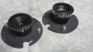
Lenses are attached to lens disc via jam nuts are directly screwed in and each disc has various sized holes depending on which lens is used. The discs are attached via 2 knurled screws and twisted in slightly and screws tightened snugly (do not over stress aluminum screws as the can strip).

Lenses in lens mounts
1. Lamphouse can be lifted with clever lift handle on left side that secures itself on a knob so that negative carriers can be inserted and film can be oriented.
2. There are two main glassless negative carriers, 2 ¼” X 2 ¼” and 35 mm. I do have a 110 carrier as well. The most recent version is black on top and aluminum on bottom with spring hinge…this works very well. The older versions are all aluminum and no spring in its hinge.
3. Negative glassless carriers can easily be inserted with lamphouse lifted and the carriers are aligned with pins in the back although the older versions require a little more care in setting against the pins and should be checked after lift handle sets down the condenser housing. The older 35mm carrier is inserted with the 4 prongs up. Note: Cannot rotate the negative carriers.

Older and newer versions of negative carriers
1. Focusing is friction type moving the lens stage up and down with round handle…there is a long bellows.
2. Condenser/lamphead can easily be moved up and down the column by loosening a large aluminum knurled Lock knob on right side. Recommend not to put much stress on the lock knob…can raise or lower head by grabbing frame instead of knob. Spring strap can be lubricated with a light coat of Vaseline.
3. An optional 3” supplemental condenser is used for 35mm with a 50mm lens (not necessary if using a 75/80mm lens). Lamphouse needs to be removed by loosening the small knurled screws on the sides, filter drawer removed, and supplemental lens is inserted with flat side down on top of the existing condenser set…the prongs stick up and assist in handling without touching the glass. This is necessary for better light concentration for 35mm or smaller formats and shorter exposure time. This procedure is very easy and takes about a minute. When switching formats remember whether to add or remove the supplemental condenser.

Bulb in housing, lens in lens mount and supplemental condenser for 35mm lens
Filter drawer is above condensers and comes in two parts…not as convenient as below lens filters. The 2nd part (top), a tiny metal frame, is probably not necessary especially for correctly sized variable contrast filters. To remove, it requires a slight lift before pulling out and insertion requires putting it in gently and lowering it into a grove to set in properly. The below lens filter holder swings out of way and filters can easily be inserted if sized appropriately. Originally meant for red filter. Works well for variable contrast filters (Ilford MG). Filters must be clean and with no scratches.

Red filter holder (below lens), Filter drawer (two parts) and column lock knobs
1. Use of light dimmer or rheostat is practical to reduce light output for modern photographic paper. Current floor/foot dimmer is set at 3 bars on slide switch which is approximately 92 volts…approximately 2/3’s light output. Heat is reduced too but never had any problem with negative buckling before reduction. May increase bulb life as well. There does not appear to be any negative consequences in using variable contrast filters as long as everything remains constant.
2. For extreme enlargements, the column can be turned around to project on the floor.
3. B-22 can be broken down and store easily in a closet. Column will need to stand upright with head locked tight. Remaining hardware can be stored in a small to medium sized box. Make sure all knobs and knurled screws are tight so they do not get lost but never over tighten.
4. Note: When enlarger is used on the Tool cart, make sure that the wheel(s) are locked to minimize vibration and movement.
5. Wonderful small enlarger…it has everything you need for Black and White photography. Simplicity in form and function…very user friendly. All functions work flawlessly and smoothly. Optional accessories and spare parts are readily available at reasonable costs because so many were made and are still plentiful. The only negative is that, because it is a condenser enlarger, that dust specks may be more visible in the final print.
Print Measurements with standard B-22:
1. With 80mm Componon lens with 2 ¼” X 2 ¼’ film
a. Max enlargement : 16 3/4” X 16 3/4 “ (7X On baseboard). Extends over baseboard.
b. For 8x 10, head is approximately 2/3’s up the column.
c. For 8X 8, head is slightly over ½ way up the column.
2. With 80mm Componon lens with 35mm film
a. Max enlargement: 7 1/8” X 10 ½” on baseboard.
3. With 80mm Componon lens with 110 film
a. Max enlargement: 3 1/8” X 4 3/8” on baseboard.
4. With 75mm Omegar lens with2 ¼” X 2 ¼” film
a. Max enlargement: 17” X 17”. Extends over baseboard.
b. 8” X 10”: 2/3’s up the column.
c. 8” X 8”: Over ½ way up the column
5. With 75mm Omegar lens with 35mm film
a. Max enlargement: 7 ½” X 11”
6. With 50mm El Nikkor or Omegar lens with 35mm film with supplemental condenser.
a. Max enlargement: 12 ½” X 18” (12.5 X). Extends over baseboard.
b. 8’ X 10”: 2/3’s up the column.
7. With 50mm lens El Nikkor or Omegar lens with 110 film with supplemental condenser.
a. Max enlargement: 6 1/8” X 8 ¼”
I have tried to think how I would improve the B22 but for the life of me I could not come with anything…it just works for me. I will say that in Florida I tend to limit myself to smaller prints and seldom go beyond 8” X 10”. It can go bigger if you are so inclined.
The following is my notes and observations of the standard version of the B22. The XL version is much longer in the column and baseboard but a lot of my notes will apply to that version as well. Hopefully this will be of some value to those who wish to try “old school” photographic printing. The KHB site has a write up and list of parts and accessories:
http://www.khbphotografix.com/omega/Enlargers/B22.htm
B22 Notes
Medium format 2 ¼” X 2 ¼” and smaller sized film formats.
Manufactured in Woodside NY by Simmon Brothers Omega, introduced in 1962 and discontinued in 1974.
Dual condenser enlarger with option of 3rd supplemental condenser for 35mm format.
For Black and White films primarily.
Triangular aluminum column with counterbalance spring typical of Omega enlargers of that era. It is essentially a scaled down version of an Omega D2 without the dual I-beam column.
Baseboard: 16” X 20” (XL version is 18” X 26”)
Column Height: 37” (XL version is 49”)
Weight: Standard version approximately 16 lbs. XL version is 19 lbs.
Manual can be found here: http://www.jollinger.com/photo/cam-coll/manuals/enlargers/omega/Enlarger Chassis B-22.pdf
Enlarger on tool cart in storage closet…almost all darkroom tools, trays, lights, timer, dimmer switch, foot switch, etc., are stored in the tool cart
Florida enlarger is set up with a Unicolor 760 Timer, a lamp foot dimmer (Set at 2/3’s light output), and a foot switch. It all rests on a Walmart Tool cart that is easily stored in a large closet and is easily moved to the bathroom…wheel(s) must be locked for stability.
Temporary darkroom set up in a bathroom
Front view with timer and dimmer switch (above timer) in bathroom. Foot switch on the floor.
Set Up:
1. Assembling is quite easy because of its size and light weight. 3 knurled screws secure the column to the baseboard with head locked on top. Those are hard steel and can be locked down tight. Some screws on the enlarger are soft aluminum so never over tighten.
2. Before attaching the condenser housing to the column, with freshly clean hands, insert condensers( 3 ½”) in the cylindrical housing (with attached lift lever ) by tilting cylinder with 1st condenser facing flat side down…orient as necessary with fingers. Lay cylinder upright with handle hang out over the table, insert collar so that it stays at the top and insert 2nd condenser with flat side up and is squarely on the three protrusions… lower the collar/condenser gently and make sure to orient so that all is even. During this process use blower to get dust out. If the supplemental 35mm condenser is used, remove filter drawer first, then lay it on top of the top condenser, flat side down and the two protrusions stick up (for removal). Make sure it lies flat and not interfered with one of the collars protrusions. Inspect for finger prints, especially on bottom condenser. Note: condensers must be very clean and scratch free or it will show up on the print.
3. Attach condenser housing ,with lift handle, to the two larger sized knurled screws on each side making sure the pivot groves of the lift handle are centered ( involves some jiggling) over the broader part of the knurled screws and that the lift handle works with no resistance once the knurled screws are tightened.
4. Alignment of Omega enlargers can be found here: http://www.jollinger.com/photo/cam-coll/manuals/enlargers/omega/Tech Service Manual - Various.pdf
5. Alignment is easy too but a Philips screwdriver and level is required…follow guidelines in Omega maintenance manual in PDF file. This will also minimize stray light as well. Pay attention to the lens stage because if the lens mounting is improperly installed, it can lead to problems.
6. After alignment, the condenser housing can be centered if necessary. One method is to have the housing empty of condensers…attach as above…insert a 2 ¼” negative carrier and look down from the top. Loosen 2 screws with screwdriver on each side on the pivot arms… let the condenser housing fall freely on the carrier centering by eye as you do this making sure there is no shadows on either corner…check for light leakage and then tighten the 4 screws…test again for leakage after condensers installed and adjust accordingly(there will be a tiny amount of leakage at best.) Alternative method #2 (and perhaps a bit easier) is to turn on enlarger with condensers in the housing. Focus on a negative first so all outlines are sharp. Remove the negative carrier with negative and center the white light in the housing so that all four dark corners appear even.
7. Attach lamphouse with PH111a, 75 watt, bulb with small knurled set screws on each side.
8. Bulb can be oriented to produce the most even light by loosening two plastic covered screws on lamphouse.
Lenses are attached to lens disc via jam nuts are directly screwed in and each disc has various sized holes depending on which lens is used. The discs are attached via 2 knurled screws and twisted in slightly and screws tightened snugly (do not over stress aluminum screws as the can strip).
Lenses in lens mounts
1. Lamphouse can be lifted with clever lift handle on left side that secures itself on a knob so that negative carriers can be inserted and film can be oriented.
2. There are two main glassless negative carriers, 2 ¼” X 2 ¼” and 35 mm. I do have a 110 carrier as well. The most recent version is black on top and aluminum on bottom with spring hinge…this works very well. The older versions are all aluminum and no spring in its hinge.
3. Negative glassless carriers can easily be inserted with lamphouse lifted and the carriers are aligned with pins in the back although the older versions require a little more care in setting against the pins and should be checked after lift handle sets down the condenser housing. The older 35mm carrier is inserted with the 4 prongs up. Note: Cannot rotate the negative carriers.
Older and newer versions of negative carriers
1. Focusing is friction type moving the lens stage up and down with round handle…there is a long bellows.
2. Condenser/lamphead can easily be moved up and down the column by loosening a large aluminum knurled Lock knob on right side. Recommend not to put much stress on the lock knob…can raise or lower head by grabbing frame instead of knob. Spring strap can be lubricated with a light coat of Vaseline.
3. An optional 3” supplemental condenser is used for 35mm with a 50mm lens (not necessary if using a 75/80mm lens). Lamphouse needs to be removed by loosening the small knurled screws on the sides, filter drawer removed, and supplemental lens is inserted with flat side down on top of the existing condenser set…the prongs stick up and assist in handling without touching the glass. This is necessary for better light concentration for 35mm or smaller formats and shorter exposure time. This procedure is very easy and takes about a minute. When switching formats remember whether to add or remove the supplemental condenser.
Bulb in housing, lens in lens mount and supplemental condenser for 35mm lens
Filter drawer is above condensers and comes in two parts…not as convenient as below lens filters. The 2nd part (top), a tiny metal frame, is probably not necessary especially for correctly sized variable contrast filters. To remove, it requires a slight lift before pulling out and insertion requires putting it in gently and lowering it into a grove to set in properly. The below lens filter holder swings out of way and filters can easily be inserted if sized appropriately. Originally meant for red filter. Works well for variable contrast filters (Ilford MG). Filters must be clean and with no scratches.
Red filter holder (below lens), Filter drawer (two parts) and column lock knobs
1. Use of light dimmer or rheostat is practical to reduce light output for modern photographic paper. Current floor/foot dimmer is set at 3 bars on slide switch which is approximately 92 volts…approximately 2/3’s light output. Heat is reduced too but never had any problem with negative buckling before reduction. May increase bulb life as well. There does not appear to be any negative consequences in using variable contrast filters as long as everything remains constant.
2. For extreme enlargements, the column can be turned around to project on the floor.
3. B-22 can be broken down and store easily in a closet. Column will need to stand upright with head locked tight. Remaining hardware can be stored in a small to medium sized box. Make sure all knobs and knurled screws are tight so they do not get lost but never over tighten.
4. Note: When enlarger is used on the Tool cart, make sure that the wheel(s) are locked to minimize vibration and movement.
5. Wonderful small enlarger…it has everything you need for Black and White photography. Simplicity in form and function…very user friendly. All functions work flawlessly and smoothly. Optional accessories and spare parts are readily available at reasonable costs because so many were made and are still plentiful. The only negative is that, because it is a condenser enlarger, that dust specks may be more visible in the final print.
Print Measurements with standard B-22:
1. With 80mm Componon lens with 2 ¼” X 2 ¼’ film
a. Max enlargement : 16 3/4” X 16 3/4 “ (7X On baseboard). Extends over baseboard.
b. For 8x 10, head is approximately 2/3’s up the column.
c. For 8X 8, head is slightly over ½ way up the column.
2. With 80mm Componon lens with 35mm film
a. Max enlargement: 7 1/8” X 10 ½” on baseboard.
3. With 80mm Componon lens with 110 film
a. Max enlargement: 3 1/8” X 4 3/8” on baseboard.
4. With 75mm Omegar lens with2 ¼” X 2 ¼” film
a. Max enlargement: 17” X 17”. Extends over baseboard.
b. 8” X 10”: 2/3’s up the column.
c. 8” X 8”: Over ½ way up the column
5. With 75mm Omegar lens with 35mm film
a. Max enlargement: 7 ½” X 11”
6. With 50mm El Nikkor or Omegar lens with 35mm film with supplemental condenser.
a. Max enlargement: 12 ½” X 18” (12.5 X). Extends over baseboard.
b. 8’ X 10”: 2/3’s up the column.
7. With 50mm lens El Nikkor or Omegar lens with 110 film with supplemental condenser.
a. Max enlargement: 6 1/8” X 8 ¼”