Olympus Pen EES-2 rescue and repair

20250427_154237.jpg

D
20250427_154237.jpg

  • 0
  • 0
  • 13
Genbaku Dome

D
Genbaku Dome

  • 2
  • 1
  • 27
City Park Pond

H
City Park Pond

  • 0
  • 1
  • 42
Icy Slough.jpg

H
Icy Slough.jpg

  • 1
  • 0
  • 40
Roses

A
Roses

  • 8
  • 0
  • 126

Recent Classifieds

Forum statistics

Threads
197,498
Messages
2,759,969
Members
99,518
Latest member
addflo
Recent bookmarks
0

bernard_L

Member
Joined
Feb 17, 2008
Messages
1,959
Format
Multi Format

Olympus Pen EES-2 rescue and repair​


Context. Bought a Pen EE -2 at a camera fair, cheap. Shot two dozen frames, cityscapes. Nice little camera, carefree, forget adjustments and just think about subject and composition. But was frustrated with no focus: depth of field can't be that large, so sharpness is a lottery for near- and mid-range subjects. GAS-sing for a Pen EES-2 with focus adjust; no way I would pay the going prices on the auction site. So I bought one "for parts" camera, stated as "shutter inoperative"; should be easy: dis-assembly, naphta, wipe, re-assemble.

The camera I received had been tampered by an idiot; in French we call them blaireau (badger). The "tower" parts of the lens cylinder was mounted with random orientations, tilting sideways like the tower of Pisa; screws were missing; and worse of all the blaireau had punched a hole through one shutter blade. The protruding edges of the hole were blocking the motion of the blade; the shutter cycle could not complete.

1728826569408.png


I give below some information on my repair. I benefitted from valuable and detailed information given by Mikeno62 on his youtube channel:

especially parts 1 and 4. My memo is not a detailed step-by-step procedure but focuses on key points.

Separate lens assembly from body

The lens assemby is held on the body primarily by the four screws around the shutter, behind the film gate (see pic above), but also by the two plates in front, below the leatherette. One also needs to remove the top and bottom body covers. My experience was: (a) remove the four screws at the back; lens is loose but not free; (b) remove the two front plates; (c) separate the lens from body (except for the wires).

Dismantling of lens "tower"

This means the pile of rings for ASA/ISO, distance, AUTO/f-stop. First remove the front element; see the video by Mikeno62 starting at 3'03" to preserve the infinity setting. In my case, given the sad state of that camera, there was most likely nothing to preserve. Remove the photocell assembly (see below about wiring). Then proceed. Caution: two of the black rings have a small bearing ball for click stops; they are normally held in place by a little grease. Clean the rings from accumulated dust/crud.

About wiring.

You don't want to do repair work with all the wiring attached. And in my case, the light meter circuit wires had he insulator cracked, so I replaced them; and the sync wiring as well for good measure; the latter needs a thick enough insulator to withstand the 300V (or so) voltage of old flash units. If you do not need to replace the light meter wires, I would advise to leave alone the solder joints on the Selenium photocell: the solderable metal there is thin and if it's gone, all is lost. Also leave alone the solder joints on the galvanometer. My recommendation is to cut the wires next to the viewfinder then pull the wires and set the photocell aside; make a note of which hole the wires go through; when re-assembling protect the solder junction with shrink tube. There is a small resistor in series in the photocell circuit; I measured 4.1kΩ but the value might be different, chosen on the assembly line to mitigate photocell tolerance.

Besides the photocell, other solder points are delicate: the sync contact on the shutter and the sync contact in the hot shoe, because of nearby thermoplastic parts. I used a small 12W iron, but in retrospect it would have been better to use a bigger iron to minimize the soldering time.

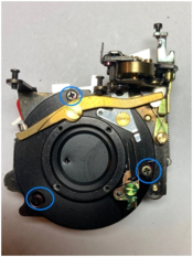
Repair of shutter blade

See below a picture of the lens+shutter assembly. The indicated three screws hold the shutter blade support plate. After removing the screws, hold the two parts together and flip over, then lift the assembly, revealing the shutter blade plate. The blades are 50µm (2mil) thick.

With the damaged blade on a flat surface, I sanded the burrs on the edge of the hole with P600 (EU grade) grit sandpaper. Then I glued a patch of 15µM (0.6 mil) copper-beryllium, with cyanoacrylate, using polyethylene sheets (cut from a Ziploc bag) to press the patch while the glue was setting. There is still a small hump, but the height of the blade housing is sufficient to accommodate it. The important point is that the patch extends out beyond the edge of the opening so it never has to go over a step when the blades open.

1728826758828.jpeg
1728826641595.png


1728826662136.png
 

Attachments

  • 1728826620499.png
    1728826620499.png
    135.9 KB · Views: 13
Last edited by a moderator:
OP
OP
bernard_L

bernard_L

Member
Joined
Feb 17, 2008
Messages
1,959
Format
Multi Format
Continued

Access to inner optical surfaces.


Before re-assembling the lens, check the optics for cleanliness. The lens is four elements, three groups, presumably Tessar-like. This lens is not well protected from dust. With dis-assembly so far, you have access to: both sides of the front element, the front of the center element, and, with the shutter blade support plate dis-mounted, to the rear of the rear group. This leaves two optical surfaces potentially dusty. First, open the diaphragm to have a clear view, using a piece of card or heavy stock paper as shown below, and have a look. If cleaning is needed remove the three screws indicated. Then, using a spanner, remove the rear group; you now have access to the back surface of the middle element (keeping the diaphragm open) and to the front of the rear group. Clean gently. Better not try to remove the diaphragm sub-assembly; re-assembly is tricky.

1728826964949.jpeg


Next pic shows the maximum dis-assembly that I reached. Mikeno62 went farther, down to every screw and hairspring.

1728827013481.jpeg


Re-assembly

Now re-assemble in reverse order, with some caveats.

Proper placement of parts on the back side of the lens/shutter assembly. See below. (A) The long brass lever should, at the left end, be below the shiny steel arm protruding from the front; this carries to the left side the information that the shutter should go to "fast" (1/200). (B) Make sure the small spring is in place at both ends. (C) The brass gear on top can be turned by hand to arm the shutter. (D) A lever can pivot around the point of the green arrow, when (1) the shutter release is depressed and (2) it is allowed to do so by the long brass lever (mentioned just above); it will then dis-engage the brass cylinder from the shutter motion, enabling the fast shutter speed with reduced inertia. In my case, the hairpin spring was not strong enough; I had to bend it to make it functional.

1728827129780.jpeg
 
Last edited:
OP
OP
bernard_L

bernard_L

Member
Joined
Feb 17, 2008
Messages
1,959
Format
Multi Format
Continued

Checking the auto diaphragm and shutter operation.
How can you do with the photocell dis-connected? Simulate the presence of the galvanometer needle with a piece of card or other. Do not mess with the real galva needle! See picture below. A piece of thin-gauge single-strand wire would allow a more precise definition of the operating point. Check for the proper changes of aperture, and the changeover to fast shutter, either by ear, or seeing that the brass retard cylinder does not move, or with an electronic timer. In my case both speeds (1/40, 1/200) are approx. 10% slow, i.e. 1/6 EV. Not bad for a camera aged 50+ years.

IMG_3365_cr.jpg


Pen.png


Next, the assembly of the "tower"; the parts are shown below, in the correct order, left-right, top-bottom on the picture. Green: the two bearing balls that you have not lost. Magenta the fork for connecting the front lens element to the distance scale. Orange: this short finger is on the ASA/ISO ring and engages with a fork on the rotating mask in the photocell sub-assembly. Unfortunately, the rings are shown in random orientations on the group portrait.

IMG_3374_S.jpg


Next is the assembly sequence, properly oriented. Start with the Auto/manual aperture wheel; e.g. in the "A" position, where it engages a click detent on a spring extending from the shutter assembly below. Then the other four wheels in sequence as shown on the four pictures. Grease lightly the surfaces where they slide against another.

Finally the photocell assembly; ensure that the fork on the rotating darkslide engages the tab on the ISO/ASA scale.

IMG_3377_S.jpg


IMG_3378_S.jpg


IMG_3379_S.jpg


IMG_3380_S.jpg


Coming soon : How to calibrate focus on a camera with only 1/40, 1/200 and no B setting?
 
OP
OP
bernard_L

bernard_L

Member
Joined
Feb 17, 2008
Messages
1,959
Format
Multi Format
Continued
Infinity calibration
. For this I need to have the shutter and diaphragm open for minutes, not milliseconds. See below a detail of the shutter timing mechanism taken when the camera was dis-assembled.

IMG_3383_S.jpg


A : gear for cocking the shutter
B : small sphere meshing with a fork in the shutter plate to actuate the blades
C : a small protrusion that rotates with the sphere B during shutter actuation
D : brass cylinder whose inertia is used to produce the slow 1/40 speed

Clearly the camera must be almost fully assembled to adjust infinity focus. The trick is to insert a small rod that will stop C about halfway through its rotation, with shutter fully open. This can be done with the top cover removed, and the galvanometer dis-mounted. to leave room for a small screwdriver. A piece of electrical wire keeps the shutter release depressed; I used single-stranded wire of the type used in old-style copper telephone wiring. Notice how the galvanometer is safely stored in the film cartridge cavity. Manual diaphragm at f:2.8 should work, IIRC.

Then I performed infinity calibration using a ground glass taped tight against the inner rails, and a known good SLR. Similar to:
http://rick_oleson.tripod.com/index-123.html
except I exchange the roles of camera under test and calibration camera, i.e. have the target in the focal plane of the camera under test, like in this reference:
Note the vertical lines scribed on the ground glass to assist the operation of the slit prism. The small aperture of the half-frame Pen EES-2 just allowed the split prism of the SLR (Nikon FG20) to operate.

IMG_3386_SD.jpg


IMG_3387_S.jpg


Coming soon : The proof is in the test film.
 
OP
OP
bernard_L

bernard_L

Member
Joined
Feb 17, 2008
Messages
1,959
Format
Multi Format
Test film results

Below some images from the test film. Performed with the remainder of a Kentmere 400 cartridge, developed in D-23 1+1 13'@20°C (test of just-received Metol from Ukraine). Scanned with Nikon LS-2000. Moderate sharpening applied to partially restore the MTF of the scanner -- sharpening will not "invent" detail which is absent.

For a critical test of sharpness I should have used a slower film. I have hints that the camera is front-focusing --i.e. the best focus is closer than intended. To check for this, I need, next time, to take a picture at an oblique angle of a chicken-wire fence or a gravel alley, or... a test target.

I also see some un-evenness of exposure, and I suspect that the aperture blade that rises to catch the needle might not always move freely enough.

2024-t07-03.jpg


2024-t07-08.jpg


100% crop @2700dpi
2024-t07-08-cr.jpg
 

Andreas Thaler

Subscriber
Joined
Nov 19, 2017
Messages
4,346
Location
Vienna/Austria
Format
35mm
An excellent tutorial that will help many PEN owners here and out in the world! I hope you keep going.

The views here are the indicator of the interest of your readers 👍
 
OP
OP
bernard_L

bernard_L

Member
Joined
Feb 17, 2008
Messages
1,959
Format
Multi Format
Addendum

Some explanation of the Auto/Manual aperture setting.
Ridge A provides a click feedback in the Auto aperture position. But not only! When engaged in the corresponding notch in the aperture ring, it moves forward, and so does the arm B, that will let the Red Flag arm C rise and --if light is too low and the galvanometer needle is not captured-- blade D will move left and stop the shutter release.

In he Manual aperture positions, A and B are pushed back by the aperture ring, and C is caught, allowing to shoot in the dark.

A thought for Yoshihisa Maitani !!

IMG_3361_a.jpg
 

Donald Qualls

Subscriber
Joined
Jan 19, 2005
Messages
12,073
Location
North Carolina
Format
Multi Format
I've got an EES-2 that used to work well, but the shutter has gotten sticky again. I need to find a workspace without cat assistance and open it up again...
 
Photrio.com contains affiliate links to products. We may receive a commission for purchases made through these links.
To read our full affiliate disclosure statement please click Here.

PHOTRIO PARTNERS EQUALLY FUNDING OUR COMMUNITY:


Ilford ADOX Freestyle Photographic Stearman Press Weldon Color Lab Blue Moon Camera & Machine
Top Bottom