distributed
Member
Recently I have become interested in the design of mixing chambers for providing diffuse illumination in an enlarger. I am a total newcomer to the area, so I thought I'd start with a simple experiment.
I have built a simple paper version of the LPL mixing chamber shown at the bottom of the page here: https://theonlinephotographer.typepad.com/the_online_photographer/2010/09/lpl-co.html
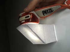
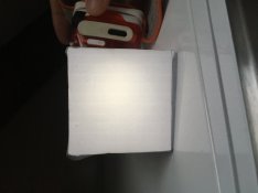
Clearly, using thin paper is not an optimal choice for actually working with the thing, but it was what I had at hand and so I went for it. You can see the result in the pictures attached to this message. The base area is 6x6 cm and covered with tracing paper, also not an optimal choice, but what I had at hand.
I put the paper mixing chamber on top of my negative carrier, shone an LED into it and measured brightness on the baseboard. I measured more than one stop of falloff between the center and the corners, very clearly too much.
I can't claim that I expected my cheap construction to work well. What surprises me, though, is that it uses what I think is the same geometry as the linked LPL design which certainly has to be much better in order to be actually used. I cannot work out what makes the big difference. Maybe someone here has an idea?
Performing some more research, I stumbled across this page: http://www.glennview.com/durst.htm
The author builds all kinds of contraptions for darkroom use, pretty amazing stuff. On the linked page, there are multiple mentions of "variable density diffusion sheets", the author even makes these sheets himself. This got me thinking: Is it possible that mixing chambers like e.g. the LPL one only achieve even output at the last moment, through the mentioned variable density diffusion sheets? I understand them to be roughly equivalent to a diffusion sheet with an inbuilt center filter. Can someone familiar with the design of mixing chambers, ahum, enlighten me?


