ThePhotoChemist
Member
Hey everyone,
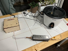
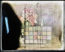
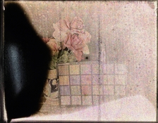
I've been working on a glass plate coating machine. I've been frustrated with my attempts to coat panchromatic emulsions onto my autochrome plates, as it tends to be very messy. It has held me back from exploring higher ISO emulsions (as I still need to use a dim safelight to see what I'm doing and I want to avoid fog), and in some cases I can't post-panchromatize the plates after coating due to the screen's sensitivity to even small amounts of alcohol. I thought it would be a fun challenge to try and make a machine that can coat an emulsion on to glass plates.
If you want to skip all the rambling and just want to see it run, skip to the end of this post. Currently the coater does run, but the quality of the coats isn't good enough for actual tests with a silver gelatin emulsion.
Initial Thoughts
I was looking around at ideas for a coating machine, checking out modern designs as well as designs that were used to coat plates 100 years ago. I don't like the idea of using a "doctor blade" to scrape a thin film across the glass, as this requires a lot of excess emulsion to run off the sides of the glass plate (which gets all over the place). It seems like that design works better for larger, continuous processes where a large piece of glass would be coated and then cut up into smaller pieces. Right now that sort of workflow doesn't make sense for me, as my autochrome press limits me to a maximum plates size of about 8x10.
I saw this video of a laboratory slot die coater, which got me excited at the possibilities:
Searching around, I saw this product for sale: https://www.mtixtl.com/MSK-FSC-I.aspx
I don't know how much that unit goes for, but based off the prices of their other products, I'm guessing it's in the $5000-$8000 range. And I thought, hey, that doesn't look too complicated, and I'd bet the amount of precision required isn't as high as that machine delivers.
The Conveyor
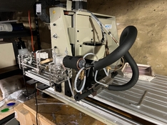
Instead of having a static surface with the coating blade moving across the plate, I figured it would be easier to have the coating blade be static and to run plates underneath it. I found this super cheap conveyor on eBay. I made some small modifications to it to suit my needs. Firstly, it was geared very highly, and ran quite fast. Secondly, it tended to "lurch" a bit and run at inconsistent speeds. My first thought was to swap the two sprockets, to give the system more torque and reduce its top speed. I was unhappy to find out that the axels for each sprocket did not match (10mm and 12mm), so I also had to buy two couplers and a few inches of rod to allow the two sprockets to be swapped.

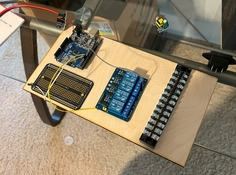
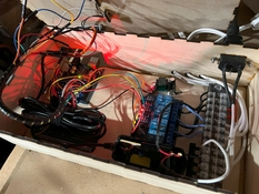
I wanted to be able to interface the motor controller with an Arduino to control start, stop, direction and speed. This turned out to be pretty easy to do. To control for direction, there is a jumper on the bottom of the controller on a terminal marked "COM", "CW", and "CCW". Moving the jumper between COM and CW or COM to CCW, unsurprisingly, changed direction. If anyone out there in the future wants to try this, be careful, as this jumper is energized to 120V! I set up a bunch of relay modules attached to the Arduino. These relays have 3 terminals - Common, a NO (normally open) and NC (normally closed). For those unfamiliar with relays, when it is not energized, there is a connection going from the Common terminal to the NC, and when it is energized the connection goes from Common to NO. By running wires from the CW and CCW termainsl to the NO and NC terminals, and connecting the two common terminals, we can easily switch between the two directions.
The On/Off switch to the controller fortunately only runs at 5V. I desoldered one of the wires on the switch and ran two to the NO and Common terminals of another relay. This lets the Arduino regulate when it wants the belt to start and stop.
The speed of the belt on the controller is regulated by a knob. The knob was attached to an 18K potentiometer which controlled a signal of 0-5V back to the controller board. I desoldered the pot and connected a DS3502 10K digital potentiometer in its place. This allows the Arduino to send a value of 0-127 to the DS3502 over i2c, which correlates to a volatage of 0-5 volts.
The Pump
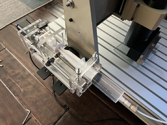
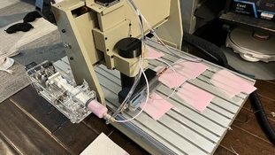
I purchased a pre-made syringe pump frame from RobotDigg. I initially tried to drive it with an L298N dual H-Bridge stepper driver, however I had issues with it skipping steps and it pulling way too much current (2.5 amps!). I ended up buying a TB6600 driver instead, and set it to use 1/16th microstepping mode. I glued a limit switch to the back of the syringe pump to allow the Arduino to "home" the axis. Since a stepper motor is controlled by a series of pulses, it is easy to know absolute position of the pump by counting the number of steps sent to the driver. I created functions to jog the pump, to allow forward and backwards movement with the Arduino's digital inputs, and then measured how many steps it takes to move the syringe plunger from the 50mL mark to the 0mL mark. This took about 15097, which factors into about 301.94 steps/mL.
The Coating Head
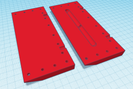
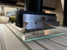
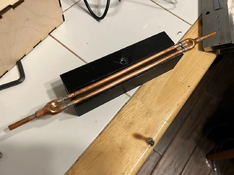
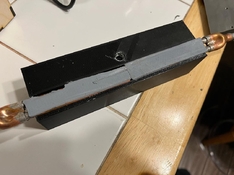
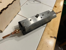
I modified an existing open-source 3d-printable slot-die head design, which can be found here: https://3dprint.com/200385/3d-printed-slot-die-system/
The OpenSCAD file took a little bit of tweaking, as it's not really designed for uses beyond 30mm coating width. I wanted to try and make a head that could coat 115-120mm (just under 5 inches), since this would allow me to maximize compatibility between 4x5 and 5x7 formats without too much bother.

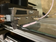
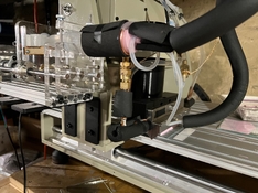
I printed out a sheath for it to slide in to, and added some thumbscrews to allow for a finer control of the coating height.
The Plate Sensor
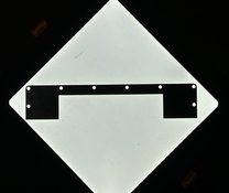
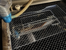
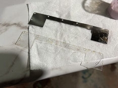
I juggled through a few different ways of detecting a plate's presence in the dark. I was wary of IR sensors, as I didn't want to nuke any of the emulsion with IR light just in case it had a slight sensitivity to it. I ended up going with a capacitive prox sensor that are common on "auto-leveling" 3d printers, since I knew it had the ability to detect glass objects without the need for any light. I laser cut a quick'n'dirty holder for the switch. The prox switch requires 12v (technically 6-36v) to operate, so I used an optocoupler to allow the Arduino to read a 5V signal.

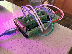
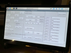
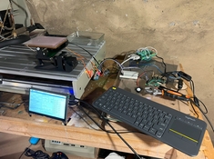
And here's the brains of it all.

The general order of operation is:
1. Place the plate against a brace in the staging area. The brace allows the user to line up the plate to the coating head correctly without needing to see what you're doing.
2. Hit the start button. The conveyor will start to run at a set speed.
3. The prox switch detects the glass plate passing beneath it. It takes a timestamp of the first edge, as well as the length of the pulse. This information can be used to calculate when the pump should start pumping, and for how long.
4. The plate passes beneath the coating head, and the syringe pump delivers a dose.
5. The plate travels along the rest of the conveyor, and comes to a stop at the end. In the future I may choose to blow cold air across the plate to allow the gelatin to gel up.
Here's a video of a dry run of the process:
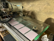
And here's a run on a few 4x5s. I made a green gelatin solution (4.5%) to make it easier to see the coating quality.
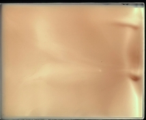
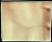
Resulting plates:

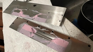
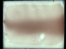
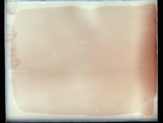
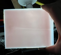
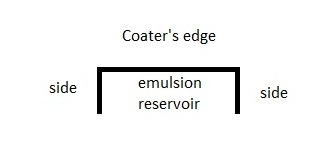
So, what went wrong? I'm guessing the coating head just doesn't scale very well when you get to larger sizes. Instead of coming down in a sheet, you could see areas where more gelatin would come out than others. Almost none came out of the far edges of the coater. My next step is to redesign the coater head to be more reminiscent to that of a proper metal one, with two halves separated by 100um shims. I can also add a meniscus guide, which I guess will help... guide the meniscus? Hopefully with the next design will at least reach a full 5in coating width. If anyone has any resources that they think could help me out with the coating head definitely feel free to let me know.
Next Steps
Besides the coater redesign, I would like to add a basic cleaning function to the system. Using a 3-way solenoid valve, it would be possible to have the pump load up the emulsion automatically, and then deliver the dosage through a different tube. In the same manner, a tube going to a container full of hot water would allow the pump to suck up the water, and push it through the coating system to clean the head out while in the dark.
I'm also thinking about adding in a rotary encoder on to the belt motor's axis. Another dedicated arduino would be able to measure the spinning speed of the motor. Right now the motor is an "open loop", meaning the controller doesn't have any sort of feedback as to how fast the motor is actually spinning. Right now the speed is very consistent, but down the line, as gunk gets into the belt and bearings wear, slight differences in speed could result in timing mismatches between the pump and the plate. At the very least the user could periodically check the coating speed and ensure that it's running at the correct amount of RPMs.
I've been working on a glass plate coating machine. I've been frustrated with my attempts to coat panchromatic emulsions onto my autochrome plates, as it tends to be very messy. It has held me back from exploring higher ISO emulsions (as I still need to use a dim safelight to see what I'm doing and I want to avoid fog), and in some cases I can't post-panchromatize the plates after coating due to the screen's sensitivity to even small amounts of alcohol. I thought it would be a fun challenge to try and make a machine that can coat an emulsion on to glass plates.
If you want to skip all the rambling and just want to see it run, skip to the end of this post. Currently the coater does run, but the quality of the coats isn't good enough for actual tests with a silver gelatin emulsion.
Initial Thoughts
I was looking around at ideas for a coating machine, checking out modern designs as well as designs that were used to coat plates 100 years ago. I don't like the idea of using a "doctor blade" to scrape a thin film across the glass, as this requires a lot of excess emulsion to run off the sides of the glass plate (which gets all over the place). It seems like that design works better for larger, continuous processes where a large piece of glass would be coated and then cut up into smaller pieces. Right now that sort of workflow doesn't make sense for me, as my autochrome press limits me to a maximum plates size of about 8x10.
I saw this video of a laboratory slot die coater, which got me excited at the possibilities:
Searching around, I saw this product for sale: https://www.mtixtl.com/MSK-FSC-I.aspx
I don't know how much that unit goes for, but based off the prices of their other products, I'm guessing it's in the $5000-$8000 range. And I thought, hey, that doesn't look too complicated, and I'd bet the amount of precision required isn't as high as that machine delivers.
The Conveyor
Instead of having a static surface with the coating blade moving across the plate, I figured it would be easier to have the coating blade be static and to run plates underneath it. I found this super cheap conveyor on eBay. I made some small modifications to it to suit my needs. Firstly, it was geared very highly, and ran quite fast. Secondly, it tended to "lurch" a bit and run at inconsistent speeds. My first thought was to swap the two sprockets, to give the system more torque and reduce its top speed. I was unhappy to find out that the axels for each sprocket did not match (10mm and 12mm), so I also had to buy two couplers and a few inches of rod to allow the two sprockets to be swapped.
I wanted to be able to interface the motor controller with an Arduino to control start, stop, direction and speed. This turned out to be pretty easy to do. To control for direction, there is a jumper on the bottom of the controller on a terminal marked "COM", "CW", and "CCW". Moving the jumper between COM and CW or COM to CCW, unsurprisingly, changed direction. If anyone out there in the future wants to try this, be careful, as this jumper is energized to 120V! I set up a bunch of relay modules attached to the Arduino. These relays have 3 terminals - Common, a NO (normally open) and NC (normally closed). For those unfamiliar with relays, when it is not energized, there is a connection going from the Common terminal to the NC, and when it is energized the connection goes from Common to NO. By running wires from the CW and CCW termainsl to the NO and NC terminals, and connecting the two common terminals, we can easily switch between the two directions.
The On/Off switch to the controller fortunately only runs at 5V. I desoldered one of the wires on the switch and ran two to the NO and Common terminals of another relay. This lets the Arduino regulate when it wants the belt to start and stop.
The speed of the belt on the controller is regulated by a knob. The knob was attached to an 18K potentiometer which controlled a signal of 0-5V back to the controller board. I desoldered the pot and connected a DS3502 10K digital potentiometer in its place. This allows the Arduino to send a value of 0-127 to the DS3502 over i2c, which correlates to a volatage of 0-5 volts.
The Pump
I purchased a pre-made syringe pump frame from RobotDigg. I initially tried to drive it with an L298N dual H-Bridge stepper driver, however I had issues with it skipping steps and it pulling way too much current (2.5 amps!). I ended up buying a TB6600 driver instead, and set it to use 1/16th microstepping mode. I glued a limit switch to the back of the syringe pump to allow the Arduino to "home" the axis. Since a stepper motor is controlled by a series of pulses, it is easy to know absolute position of the pump by counting the number of steps sent to the driver. I created functions to jog the pump, to allow forward and backwards movement with the Arduino's digital inputs, and then measured how many steps it takes to move the syringe plunger from the 50mL mark to the 0mL mark. This took about 15097, which factors into about 301.94 steps/mL.
The Coating Head
I modified an existing open-source 3d-printable slot-die head design, which can be found here: https://3dprint.com/200385/3d-printed-slot-die-system/
The OpenSCAD file took a little bit of tweaking, as it's not really designed for uses beyond 30mm coating width. I wanted to try and make a head that could coat 115-120mm (just under 5 inches), since this would allow me to maximize compatibility between 4x5 and 5x7 formats without too much bother.
I printed out a sheath for it to slide in to, and added some thumbscrews to allow for a finer control of the coating height.
The Plate Sensor
I juggled through a few different ways of detecting a plate's presence in the dark. I was wary of IR sensors, as I didn't want to nuke any of the emulsion with IR light just in case it had a slight sensitivity to it. I ended up going with a capacitive prox sensor that are common on "auto-leveling" 3d printers, since I knew it had the ability to detect glass objects without the need for any light. I laser cut a quick'n'dirty holder for the switch. The prox switch requires 12v (technically 6-36v) to operate, so I used an optocoupler to allow the Arduino to read a 5V signal.
And here's the brains of it all.
The general order of operation is:
1. Place the plate against a brace in the staging area. The brace allows the user to line up the plate to the coating head correctly without needing to see what you're doing.
2. Hit the start button. The conveyor will start to run at a set speed.
3. The prox switch detects the glass plate passing beneath it. It takes a timestamp of the first edge, as well as the length of the pulse. This information can be used to calculate when the pump should start pumping, and for how long.
4. The plate passes beneath the coating head, and the syringe pump delivers a dose.
5. The plate travels along the rest of the conveyor, and comes to a stop at the end. In the future I may choose to blow cold air across the plate to allow the gelatin to gel up.
Here's a video of a dry run of the process:
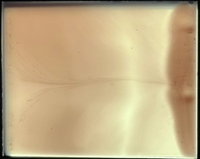
And here's a run on a few 4x5s. I made a green gelatin solution (4.5%) to make it easier to see the coating quality.
Resulting plates:
So, what went wrong? I'm guessing the coating head just doesn't scale very well when you get to larger sizes. Instead of coming down in a sheet, you could see areas where more gelatin would come out than others. Almost none came out of the far edges of the coater. My next step is to redesign the coater head to be more reminiscent to that of a proper metal one, with two halves separated by 100um shims. I can also add a meniscus guide, which I guess will help... guide the meniscus? Hopefully with the next design will at least reach a full 5in coating width. If anyone has any resources that they think could help me out with the coating head definitely feel free to let me know.
Next Steps
Besides the coater redesign, I would like to add a basic cleaning function to the system. Using a 3-way solenoid valve, it would be possible to have the pump load up the emulsion automatically, and then deliver the dosage through a different tube. In the same manner, a tube going to a container full of hot water would allow the pump to suck up the water, and push it through the coating system to clean the head out while in the dark.
I'm also thinking about adding in a rotary encoder on to the belt motor's axis. Another dedicated arduino would be able to measure the spinning speed of the motor. Right now the motor is an "open loop", meaning the controller doesn't have any sort of feedback as to how fast the motor is actually spinning. Right now the speed is very consistent, but down the line, as gunk gets into the belt and bearings wear, slight differences in speed could result in timing mismatches between the pump and the plate. At the very least the user could periodically check the coating speed and ensure that it's running at the correct amount of RPMs.
Attachments
Last edited:


