


Hello all,
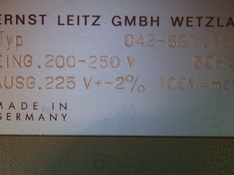
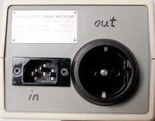
I bought a Leitz Voltage Stabilizer Type 042-827.251 off eBay recently. Its a transformer-based device meant to regulate mains voltage down to a stable AC 225V+/- 2% no matter the input voltage (within 200-250V AC). The device is particular interesting to me because it does two things: bucking down to 225V AND keeping that potential constant - both very useful when enlarging with 220V rated bulbs of yesteryear. There are many new small stabilizers devices available which buck/boost (or the simpler ones just cut off) but all of them swing with the mains fluctuations (which does it a lot here over the day) or switch transformer taps physically. This one ought not to and promises to be accurate with 2% of 225V out.
At any rate, I got the thing and plugged it into my isolation transformer/lab power supply set to 230V and measured the output voltage. It read 250V (uugh! ought to be 225). I regulated the input from 200 to 240V and sure enough it kept the 250V output stable. So it seems to work basically.
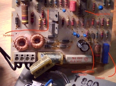
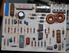
Wondering why it transformed the voltage up to 250V (instead down to 225V), I went ahead and opened it, as something certainly is not right. The board looked good at first sight. The input-safety cap has a small break/fissure in the insulation, but given the age and type of cap (RIFA from the 70ties) that has to be expected (we call them "Knallfrosch" around here literally "poping frog" as they tend to explode). Anyways, I spotted a trimmer (blue thing) on the board and figured its for fine tuning the output voltage regulation. So I carefully turned it and watched the output. Sure enough it went down with each turn. After approaching 230V though... the inevitable happened, the frog popped and smokes went up in the air. Yikes. Everything else looks good on the board, so keeping fingers crossed its just the cap (after all its a safety cap and failure mode is to prevent continuity and fire).
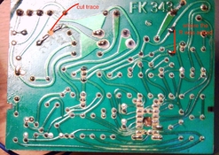
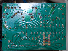
It might have been coincidence it popped when it did (while messing with the trimmer), but I am not certain. I checked the board. It looks like it has been tampered with. A trace was cut and it looks to me like a resistor was added in parallel to a diode (see pics). Maybe that's the explanation why it outputs 250V instead fo 225V? Maybe the circuit was modified for a 250V country? It might be tampering but it might also be a change/improvement added in the factory after board production (not uncommon).
As an afterhought, now I am writing this: I measured the output with a Fluke multimeter which is high ohms impedance device. So maybe I was misinterpreting the reading as there was no load applied (idle Voltage higher than under load). But with a regulated supply that should not happen - the output should be constant no matter the load (at least that's what the DC regulators do). I did not have a chance to test with a Duspol which can apply a load (or a actual bulb for that matter). Could that be a factor I misjudged? I mean the 250V being the unloaded output which goes down to 225V and with a load? And everything would have been in spec in the first place?
I simply don't know. I have little experience with those kinds of circuits.
Long story short, I need your help:
- does anyone have a schematic or service manual of the thing?
- maybe someone owns one of those and would be so nice to post detailed photos of the board (both sides)?
- does anyone know what kind of circuits this is (basic type/design, it does not seem to be just a simple phase dimmer with the transformer and all)
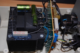
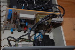
I could identify some of the silicon (all discrete/analog): CA3046 (transistor array), BC02B (transistor), 2x CS3-06DO2 (thyristor). Then there are two inductors (to one of them the trace is cut). Lots of small diodes and resistors (power and smaller) an electrolytic cap (probably rectifier/ripple filter for getting LV supply for the silicon). Ah, and then there's the largish transformer which seems to have uneven windings (or core size on the primary/secondary) and some foil caps between the windings (i'll take a picture later). The input goes to the board, then the board is connected to the transformer, the output comes from the same transformer windings the input goes to (which makes me suspect the mode of operation is something like the other winding is somehow used to influence the efficiency of the primary winding by means of some resonance or phase shifting tricks. Or something like that anyways, just guessing. I've read up a bit on voltage stabilizers, abut nothing I found online seems to match this circuit design.
I am dedicated to repair this piece of equipment and get it working properly again. I certainly will replace the X cap, electrolytic, and the carbon comp power resistors (with wirewounds or mox).
So any help and insights very much appreciated.
Kinds regards,
Andi
PS: Added more detailed images
I bought a Leitz Voltage Stabilizer Type 042-827.251 off eBay recently. Its a transformer-based device meant to regulate mains voltage down to a stable AC 225V+/- 2% no matter the input voltage (within 200-250V AC). The device is particular interesting to me because it does two things: bucking down to 225V AND keeping that potential constant - both very useful when enlarging with 220V rated bulbs of yesteryear. There are many new small stabilizers devices available which buck/boost (or the simpler ones just cut off) but all of them swing with the mains fluctuations (which does it a lot here over the day) or switch transformer taps physically. This one ought not to and promises to be accurate with 2% of 225V out.
At any rate, I got the thing and plugged it into my isolation transformer/lab power supply set to 230V and measured the output voltage. It read 250V (uugh! ought to be 225). I regulated the input from 200 to 240V and sure enough it kept the 250V output stable. So it seems to work basically.
Wondering why it transformed the voltage up to 250V (instead down to 225V), I went ahead and opened it, as something certainly is not right. The board looked good at first sight. The input-safety cap has a small break/fissure in the insulation, but given the age and type of cap (RIFA from the 70ties) that has to be expected (we call them "Knallfrosch" around here literally "poping frog" as they tend to explode). Anyways, I spotted a trimmer (blue thing) on the board and figured its for fine tuning the output voltage regulation. So I carefully turned it and watched the output. Sure enough it went down with each turn. After approaching 230V though... the inevitable happened, the frog popped and smokes went up in the air. Yikes. Everything else looks good on the board, so keeping fingers crossed its just the cap (after all its a safety cap and failure mode is to prevent continuity and fire).
It might have been coincidence it popped when it did (while messing with the trimmer), but I am not certain. I checked the board. It looks like it has been tampered with. A trace was cut and it looks to me like a resistor was added in parallel to a diode (see pics). Maybe that's the explanation why it outputs 250V instead fo 225V? Maybe the circuit was modified for a 250V country? It might be tampering but it might also be a change/improvement added in the factory after board production (not uncommon).
As an afterhought, now I am writing this: I measured the output with a Fluke multimeter which is high ohms impedance device. So maybe I was misinterpreting the reading as there was no load applied (idle Voltage higher than under load). But with a regulated supply that should not happen - the output should be constant no matter the load (at least that's what the DC regulators do). I did not have a chance to test with a Duspol which can apply a load (or a actual bulb for that matter). Could that be a factor I misjudged? I mean the 250V being the unloaded output which goes down to 225V and with a load? And everything would have been in spec in the first place?
I simply don't know. I have little experience with those kinds of circuits.
Long story short, I need your help:
- does anyone have a schematic or service manual of the thing?
- maybe someone owns one of those and would be so nice to post detailed photos of the board (both sides)?
- does anyone know what kind of circuits this is (basic type/design, it does not seem to be just a simple phase dimmer with the transformer and all)
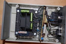
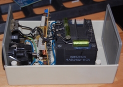
I could identify some of the silicon (all discrete/analog): CA3046 (transistor array), BC02B (transistor), 2x CS3-06DO2 (thyristor). Then there are two inductors (to one of them the trace is cut). Lots of small diodes and resistors (power and smaller) an electrolytic cap (probably rectifier/ripple filter for getting LV supply for the silicon). Ah, and then there's the largish transformer which seems to have uneven windings (or core size on the primary/secondary) and some foil caps between the windings (i'll take a picture later). The input goes to the board, then the board is connected to the transformer, the output comes from the same transformer windings the input goes to (which makes me suspect the mode of operation is something like the other winding is somehow used to influence the efficiency of the primary winding by means of some resonance or phase shifting tricks. Or something like that anyways, just guessing. I've read up a bit on voltage stabilizers, abut nothing I found online seems to match this circuit design.
I am dedicated to repair this piece of equipment and get it working properly again. I certainly will replace the X cap, electrolytic, and the carbon comp power resistors (with wirewounds or mox).
So any help and insights very much appreciated.
Kinds regards,
Andi
PS: Added more detailed images
Attachments
-
 PICT0001_small.jpg540.1 KB · Views: 27
 -
 PICT0002_small.jpg877.1 KB · Views: 27
 -
 PICT0003_small.jpg733.3 KB · Views: 25
 -
 outside_box.png266.6 KB · Views: 27
 -
 io_small.jpg10.1 KB · Views: 21
 -
 DSC_4711_small.jpg508.8 KB · Views: 18
 -
 DSC_4713_small.jpg465 KB · Views: 18
 -
 DSC_4714_small.jpg147.7 KB · Views: 20
 -
 DSC_4716_small.jpg243.7 KB · Views: 20
 -
 DSC_4710_small.jpg550.9 KB · Views: 18
 -
 DSC_4708_small.jpg277.4 KB · Views: 23
Last edited:


