Krasnogorsk FT-2 - Mods & CLA

Old Oak

A
Old Oak

  • 0
  • 0
  • 0
Rose in small vase

D
Rose in small vase

  • 0
  • 0
  • 9
Sparrow.jpg

A
Sparrow.jpg

  • 2
  • 0
  • 77
Orlovka river valley

A
Orlovka river valley

  • 7
  • 0
  • 137
Norfolk coast - 2

A
Norfolk coast - 2

  • 6
  • 1
  • 159

Recent Classifieds

Forum statistics

Threads
197,848
Messages
2,765,703
Members
99,488
Latest member
colpe
Recent bookmarks
0

MattiS

Member
Joined
Apr 29, 2016
Messages
218
Location
Germany
Format
Multi Format
Hello,

quite some time ago I got an early 1958 model (with the dial at the camera bottom) of the FT-2 panoramic camera. After sixty years the lens did not want to swing any more, so there was obvious work ahead to bring it back to life.

Unfortunately one can´t find very much information about these cameras, so this thread might collect ideas and possible solutions for problems with this cameras.

Regards Matti

So, let´s start:

Mod - Shutter button light trap

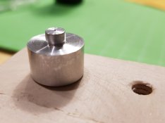
It´s reported that light can enter the camera via the shutter button. So I made a small ring on the lathe, that keeps light out of the shutter button area.
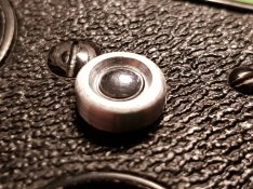
shutter_ring.jpg
 
Last edited:
OP
OP

MattiS

Member
Joined
Apr 29, 2016
Messages
218
Location
Germany
Format
Multi Format
Mod - Use of filters

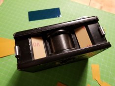
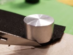
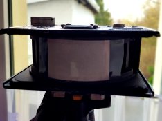
The obvious way of using filters is placing them flat in front of the camera housing. One can expect light falloff at the ends of the frame due to the large fov of the camera. Using gel filter sheets held in a curved shape seems to avoid this problem.

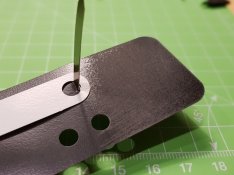
The filter holders are cut out of 1.5mm thick pcb stuff (black polystyrene sheet would be even better).

filter_0.jpg

Positioning is a bit of try and error, I fixed them with double sided adhesive tape.

filter_3.jpg

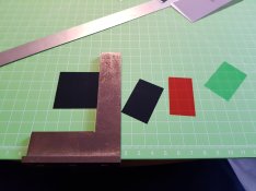
I had a pack of Strobist gel filters waiting for whatever. So I cut them to about 57x32mm which makes a nice bend in the filter that app. follows the radius of the lens drum.

filter_1.jpg filter_2.jpg

First test shots showed no light falloff.
 
Last edited:
OP
OP

MattiS

Member
Joined
Apr 29, 2016
Messages
218
Location
Germany
Format
Multi Format
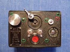
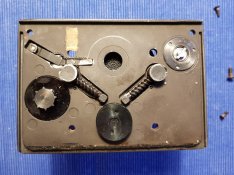
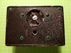
FT-2 - Removing / mounting top plate

- disengage the brakes (1/400 position)
- remove cocking lever (center screw)
- do NOT unscrew the red marked screw (it keeps the shutter lever in position)
- unscrew the six green marked srews
- take off the top plate

- top plate from underneith
-- top left: shutter mechanism (next to the shutter mechanism is one of the yellowish stickers for height adjustment of the top plate)
-- top right: film winding mechanism
-- middle left/right: brakes, left one engaged, right one disengaged (play with the brake levers to see how things work)
-- bottom left: film counter
Mounting the top plate is vice versa. If the top plate slows the lens drum movement down when you tighten the screws use cardboard pieces for spacing.


top_01.jpg top_02.jpg
 
Last edited:
OP
OP

MattiS

Member
Joined
Apr 29, 2016
Messages
218
Location
Germany
Format
Multi Format
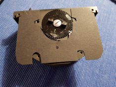
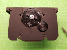
FT-2 - Removing / mounting bottom plate

- early FT-2s only:
-- write down the setting of the drive spring preload (here 1.5)
-- turn down the drive spring preload to minimum
- unscrew the six green marked srews
- take off the bottom plate
- watch out for spacer stickers /small cardboard pieces

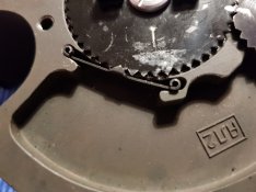
It´s just a guess, but the swing lens gear should look similar in the early and old models. Attention - even with the shutter not cocked the drive spring is preloaded. Mark the position of the gears (shutter not cocked) to each other.

Mounting the bottom plate is vice versa. If the bottom plate slows down the lens drum movement when you tighten the screws use cardboard pieces for spacing. I did not like the small original (?) cardboard pieces and cut a new, more flat spacer piece.


bottom_001.jpg bottom_002.jpg bottom_003.jpg
 
Last edited:

AgX

Member
Joined
Apr 5, 2007
Messages
29,973
Location
Germany
Format
Multi Format
One can expect light falloff at the ends of the frame due to the large fov of the camera.

I am puzzkled:
The use of a swinging lens with a slit moving over a curved mounted film just avoids any fall-off over the wide side.

Possible fall-off along the short side inherit to a WA-lens (in case such would be applied at such camera)n would not evenb be counterd by your approach, a ypi bend that filter over the long side.
 
OP
OP

MattiS

Member
Joined
Apr 29, 2016
Messages
218
Location
Germany
Format
Multi Format
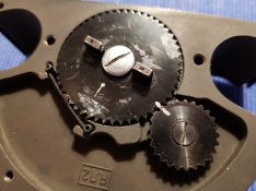
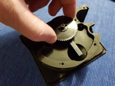
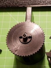
FT-2 - Removing / mounting / adjusting drive gear and spring preload

I own a 1958 copy of the FT-2. So I don´t know if the swing lens gear looks similar/identical to the one in later copies. But the general procedure should be very similar.

What has to be done in advance:
- (early FT-2s) drive spring preload original setting noted, set to minimum
- gears marked in blocked position (shutter not cocked)

Attention - the drive spring is still preloaded. To release the preload
- hold/brake the big gear with your thumb
- unscrew the center screw in the small gear, still hold and brake the big gear
- count the revolutions of the big gear when you slowly release pressure to the gear
- note the number of revolutions until the gear stops and the drive spring is unloaded.

Noting the original settings enables you to find to a good starting point for the first adjustment after reassembling.

If you want to take the swing lens assembly out of the camera, unscrew the center screw in the big gear and take it of.

Reassembling the drive gear and spring preload
- mount the big gear with the center screw on the swing lens assembly (swing lens assembly in uncocked position)
- revolve the big gear according to your notes, hold it in position
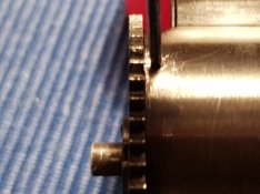
- mount the small gear so that the marks match again, fix it with the center screw

Adjusting the drive gear and spring preload
- early FT-2s - the convenient way - after the bottom plate is mounted again, set to original setting first and compare test photos at 1/400 (no brakes engaged), finetune if needed
- late FT-2s - guesstimated general procedure - turning the mark on the big gear less or beyond the mark on the small gear will reduce/increase preload. Mount the camera completely, make test shots and be happy ot start again... .


gear_01.jpg gear_02.jpg
 
Last edited:
OP
OP

MattiS

Member
Joined
Apr 29, 2016
Messages
218
Location
Germany
Format
Multi Format
I am puzzkled:
The use of a swinging lens with a slit moving over a curved mounted film just avoids any fall-off over the wide side.
.
Sorry for misunderstanding. It was meant in conjunction with the use of a flat filter. In the middle of the frame light passes the filter at 90 degrees, but not at the borders left/right making it more dense. The idea is to avoid/reduce this effect with a curved filter.
 
Last edited:

AgX

Member
Joined
Apr 5, 2007
Messages
29,973
Location
Germany
Format
Multi Format
I understand. My fault.
I have not even considered this filter-issue (as typically a filter is mounted at the swinging lens). Was faster at typing, than at thinking...

Good idea of yours!
 
OP
OP

MattiS

Member
Joined
Apr 29, 2016
Messages
218
Location
Germany
Format
Multi Format
I still have to proof it in practice. If it works fine I might modify my Horizon 202 in the same way.
 

AgX

Member
Joined
Apr 5, 2007
Messages
29,973
Location
Germany
Format
Multi Format
Only issue might bee, that, if the bend filter protrudes beyond the casing, light from behind might be reflected into the lens. But in such case two horizontal baffles can be applied,covering the space between casing and filter. A nitpicker might also address light coming from the sides.

Well, a free standing filter is a new concept as all other filters are at the end of some kind of cone. In your case the solution should be to put that curved plane as tight as possible to the casing. The radius should not be that critical.
 
OP
OP

MattiS

Member
Joined
Apr 29, 2016
Messages
218
Location
Germany
Format
Multi Format
FT-2 - Removing / mounting swing lens assembly

What has to be done in advance:
- Top/bottom plate removed
- drive gear/spring unloaded

To take the swing lens assembly out of the main casting
- unscrew the center screw in the big gear
- set the swing lens assembly to half swing and pull it out of the casting in top direction

Now the lens assembly is ready for cleaning and lubricating. If that´s what you plan to do, you´re half way through.

Any suggestions for a appropriate, non temperature sensitive lubricant are welcome (this is my very first camera mod/CLA).

Reassembling the swing lens assembly is straight forward vice versa.


drum_001.jpg drum_002.jpg
 
Last edited:
OP
OP

MattiS

Member
Joined
Apr 29, 2016
Messages
218
Location
Germany
Format
Multi Format
Only issue might bee, that, if the bend filter protrudes beyond the casing, light from behind might be reflected into the lens. But in such case two horizontal baffles can be applied,covering the space between casing and filter. A nitpicker might also address light coming from the sides.

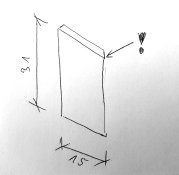
There is enough space in the casing front that the filter does not stick out. If there is need the height/width/outer shape of the gel filter could be varied to minimize stray light. See the paper model.


20200111_172832.jpg
 
Last edited:
OP
OP

MattiS

Member
Joined
Apr 29, 2016
Messages
218
Location
Germany
Format
Multi Format
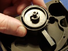
FT-2 - Removing/mounting lens carrier

What has to be done in advance:
- swing lens assembly pulled out of the main casting
- get a proper fitting screwdriver for the tiny M1.2 countersunk head screws

To pull the swing lens assembly out of the main casting
- mark the position of brake gear relative to the lens assembly "chimmney" for reassembling
- unscrew the brake gear on top of the swing lens assembly (two really tiny screws)
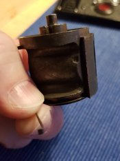
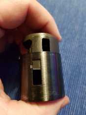
- pull the lens carrier out of the outer cylinder with the lens slots in both parts aligned

Now the lens assembly is ready for cleaning and lubricating. If that´s what you plan to do, you´re half way through.

Any suggestions for a appropriate, non temperature sensitive lubricant are welcome (this is my very first camera mod/CLA).


out_00.jpg out_01.jpg out_02.jpg


Reassembling the lens carrier back into swing lens cylinder

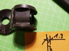
The inner and outer cylinder design is neccessary to avoid light hitting the film during cocking. A small return spring pushes both cylinders back in the correct position for exposure after cocking. This spring is located in the lower part of the lens carrier. It must hook in a small plate welded to the inside of the swing lens assembly.

Pull the spring 1-2cm out of the lens carrier, so that you can hold it and hook it from inside to outside into the outer cylinders lens slot.
Let the end of the spring flip in the cylinder and push the lens carrier (slots of both cylinders in line) gently back into the lens assembly. Check, if the spring pushes the slots in the cylinders back in line. If not, try it again. Do not use excessive force. It´s hard to explain, it may take two or three times to try, but once it´s done it´s easy to understand the simplicity of the mechanism - easier than describing it.

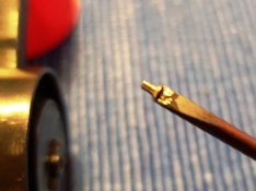
Push the brake gear on the outer cylinder and fix it with the countersunk head screws. I fixed the tiny bastards with a little bit of grease on the tip of the screwdriver. Makes handling them a lot easier.


in_01.jpg in_02.jpg in_03.jpg


to be continued with
- Aperture modification / cleaning lens
- Adjusting focus
 
OP
OP

MattiS

Member
Joined
Apr 29, 2016
Messages
218
Location
Germany
Format
Multi Format
FT-2 - Lens cleaning / aperture modification

What has to be done in advance:
- lens carrier is disassembled from the swing lens assembly
- measure the position of the lens barrel in the carrier for first setting when reassembling


aperture_001.jpg


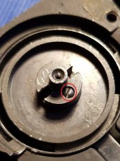
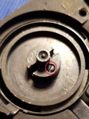
To pusl/pull the lens barrel out of the lens carrier
- loosen the small grub screw (marked red) on top of the lens carrier
- pusl/pull the lens barrel out of the lens carrier


aperture_002.jpg aperture_003.jpg aperture_004.jpg


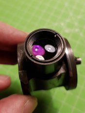
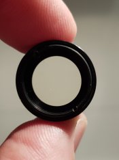
There is your lens. Ready for cleaning or...

... an aperture blade

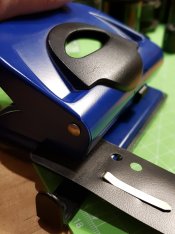
I measured the space for the aperture blade and got 2mm soft rubber and a filing clip for the parts. I also made a cutting aid on the lathe, but that was just a comfort feature.


aperture_005.jpg


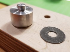
Now I had a closer look at my special aperture-hole punch. Normally it punches 5.5mm holes in Paper. 5.5mm aperture diameter in a 50mm lens is f9, and with 1/400 gives you the same EV value than f8 with 1/500. So I can frame and measure with my SLR and transfer the values to the FT-2.

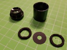
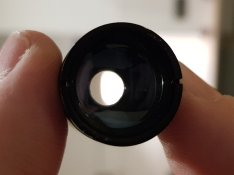
So I sanded the filing clip matte, punched the f9 hole and cut the outer diameter. Together with the two rubber rings I mounted the aperture blade in the lens barrel. I pushed the lens barrel back in it´s original position and fixed it with the grub screw.


aperture_006.jpg aperture_007.jpg aperture_008.jpg aperture_009.jpg aperture_010.jpg aperture_011.jpg aperture_012.jpg
 
OP
OP

MattiS

Member
Joined
Apr 29, 2016
Messages
218
Location
Germany
Format
Multi Format
FT-2 - Adjusting focus

Best news first - if you only want to check the focus setting for some reason there is not much to disassemble. Just
- take the camera back off
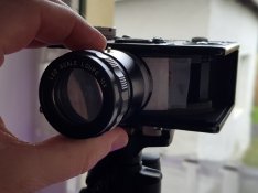
- block the swing lens assembly so that you can peep through the lens
- disassemble the cocking lever
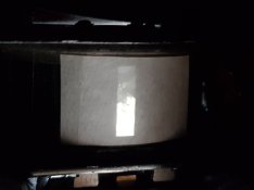
- tape a piece of thin paper on the film rails
- put the camera on a tripod
- loosen the grub screw (marked red) on top of the lens carrier
- now you can push the lens back and forward with a screwdriver
- check focus (darkcloth, loupe)
- tighten the grub screw
- assemble the camera (depending on the work steps done before)


focus_001.jpg focus_002.jpg focus_003.jpg focus_004.jpg focus_005.jpg
 
Last edited:
Joined
Mar 5, 2006
Messages
144
Location
Egg Harbor C
Format
Multi Format
(That work would take me 1000 hours, countless tries, forgetting part order, probably breaking things and the whole project ending up in a baggie. Congrats to those with the ability to do this.
 

AgX

Member
Joined
Apr 5, 2007
Messages
29,973
Location
Germany
Format
Multi Format
Even though I never came any FT across I find this guide very interesting and likely some people will it even find helpful.
 
OP
OP

MattiS

Member
Joined
Apr 29, 2016
Messages
218
Location
Germany
Format
Multi Format
Minor update

cardboard spacer
I cut the cardboard spacer (between bottom plate and main casing) in a way that also the small gear can not touch the spacer (friction, slowing down movements).


up_01.jpg


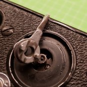
cocking lever
The marks on the body show it clearly - the cocking lever touches the body at some places. A bit of filing at the bottom of the lever solved this issue.


up_02.jpg


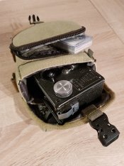
bag
This Kalahari bag waited for a new camera. Fits perfect, unfortunately it seems to be out of production.


Up_03.jpg
 
Last edited:

kmcsmart

Subscriber
Joined
Jan 4, 2023
Messages
30
Location
Ontario, Canada
Format
Hybrid
This thread is fantastic! I couldn’t find information about an CLA in the FT-2 anywhere. Thanks so much.

I have a question about removing the lens carrier. I was able to remove the two screws but I can’t get the brake gear to move in any way. I’m not sure where to pull and push to get lens carrier apart. Does it come apart where I have marked the 2 green arrows or only at the brake gear? Also are my two slots aligned correctly at the blue arrow or do they have to be perfectly aligned? I’m not sure what I am doing wrong. I put some lighter fluid at the two joints marked with the green arrows to loosen any old grease.

Any help would be appreciated. Thanks again.
 

Attachments

  • IMG_1672.jpeg
    IMG_1672.jpeg
    964.8 KB · Views: 58

kmcsmart

Subscriber
Joined
Jan 4, 2023
Messages
30
Location
Ontario, Canada
Format
Hybrid
Ok, I figured it out. Only the brake gear comes off. I wedged a screw driver against the chimney and I was able to pry off the brake gear.
 

kmcsmart

Subscriber
Joined
Jan 4, 2023
Messages
30
Location
Ontario, Canada
Format
Hybrid
Hello,

quite some time ago I got an early 1958 model (with the dial at the camera bottom) of the FT-2 panoramic camera. After sixty years the lens did not want to swing any more, so there was obvious work ahead to bring it back to life.

Unfortunately one can´t find very much information about these cameras, so this thread might collect ideas and possible solutions for problems with this cameras.

Regards Matti

So, let´s start:

Mod - Shutter button light trap

It´s reported that light can enter the camera via the shutter button. So I made a small ring on the lathe, that keeps light out of the shutter button area.

View attachment 238297

I like your shutter button shield, great idea. When I hold my top plate up to the light I can clearly see light coming through my shutter button when it is moved from side to side.
I have a lathe so I could turn a ring for my shutter button as well. I’m wondering how you attached the exterior ring to the camera?
 
OP
OP

MattiS

Member
Joined
Apr 29, 2016
Messages
218
Location
Germany
Format
Multi Format
I simply glued the ring with a contact adhesive to the camera body. Works fine, three years later it's still there.
 
Photrio.com contains affiliate links to products. We may receive a commission for purchases made through these links.
To read our full affiliate disclosure statement please click Here.

PHOTRIO PARTNERS EQUALLY FUNDING OUR COMMUNITY:



Ilford ADOX Freestyle Photographic Stearman Press Weldon Color Lab Blue Moon Camera & Machine
Top Bottom