


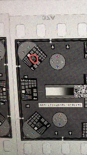
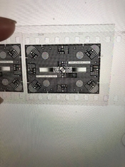
I used alignemnt film and compared the corner sharpness of the glass film carrier and the glassless film carrier at 14x magnification(around 16x20). It can be found that the glassless carrier cannot get sharpness in the corners. Only when the magnification is below 7x can it get the sharpness from the corners. Center-to-Corner Clarity


You are using an out of date browser. It may not display this or other websites correctly.
You should upgrade or use an alternative browser.
You should upgrade or use an alternative browser.
Enlarger alignment
-
A
- Thread starter yya
- Start date


Recent Classifieds
-
For Sale Essentially new in box Nikon FM10
- Started by Gram Nylén
-
For Sale Hasselblad PM90 Finder
- Started by dankapsner
-
For Sale FS: Fujinon-T 400mm f/8 Lens
- Started by B.S.Kumar
-
For Sale FS: Fujinon-W 250mm f/6.7 Lens
- Started by B.S.Kumar
-
For Sale FS: Arca-Swiss Oschwald Wide Angle Bellows (171mm square for 4x5 Cameras)
- Started by B.S.Kumar
Forum statistics
That is why glass negative carriers are so desirable.
correct!Only by testing it yourself can you know the importance of glass
correct!Only by testing it yourself can you know the importance of glass
...or a Beseler Nega-Flat.
mshchem
Subscriber
I rarely enlarge much beyond 4-5X.
I rarely enlarge much beyond 4-5X.
For me, 135 enlarging on 8x10, 120 and 4x5 enlarging on 11x14, or 4x5 on 16x20, they are under 6x
BMbikerider
Member
It is important to get you enlarger well and truly vertical with the baseboard the column and the head. I do this manually with an accurate spirit level ans where I can adjust via screws on the enlarger head I do so. But if the column is not vertical compared to the baseboard I correct this with shims of very thin spring steel at various points. The head is usually the easiest to do and I can say mine is as near perfect as possible.
If it were wall mounted it is a different ball game. It is done the same way with a spirit level but you have to check how level your table is below the enlarger and work upwards from there. If the table is floor standing you have to get that level first and work from there upwards and this can take a considerable time.
I also agree with using glass to keep the negative flat. I have adopted my LPL7700 with a glass plate 'borrowed' from an anti Newton Ring glass slide mount which is fixed permanently under the top of the glassless film carrier intended for 6x6 negatives and bears directly onto the upper surface of the film. I have never had one shift out of focus with either heat of anything else I also use a removable metal 35mm mask underneath for when I am using 35mm. That way you only have 2 glass surfaces to keep dust free instead of 4. It is/was simple to make and it works for me.
Of course it may have another quite simple explanation...... your enlarging lens (You don't say what it is) may not be 'top quality' You need something from the stables of Schneider or Rodenstock to ensure you get the best (I use a Rodenstock 50/2,8 apo which I cannot fault. for 6x6 I have a Nikon 80mm F5.6 which is almost as good.


It is important to get you enlarger well and truly vertical with the baseboard the column and the head. I do this manually with an accurate spirit level ans where I can adjust via screws on the enlarger head I do so. But if the column is not vertical compared to the baseboard I correct this with shims of very thin spring steel at various points. The head is usually the easiest to do and I can say mine is as near perfect as possible.
If it were wall mounted it is a different ball game. It is done the same way with a spirit level but you have to check how level your table is below the enlarger and work upwards from there. If the table is floor standing you have to get that level first and work from there upwards and this can take a considerable time.
I also agree with using glass to keep the negative flat. I have adopted my LPL7700 with a glass plate 'borrowed' from an anti Newton Ring glass slide mount which is fixed permanently under the top of the glassless film carrier intended for 6x6 negatives and bears directly onto the upper surface of the film. I have never had one shift out of focus with either heat of anything else I also use a removable metal 35mm mask underneath for when I am using 35mm. That way you only have 2 glass surfaces to keep dust free instead of 4. It is/was simple to make and it works for me.
Of course it may have another quite simple explanation...... your enlarging lens (You don't say what it is) may not be 'top quality' You need something from the stables of Schneider or Rodenstock to ensure you get the best (I use a Rodenstock 50/2,8 apo which I cannot fault. for 6x6 I have a Nikon 80mm F5.6 which is almost as good.
If you use a laser device you may get different results, I mean a level is sometimes not as accurate as a laser, no matter what, I think using alignment film is the most direct and quickest way to check alignment. However, when you find that it is not aligned, you may need to make adjustments through other methods. Film cannot help you adjust the enlarger.
mfagan
Subscriber
I laser align my glass negative carrier to the baseboard and also the lens axis to the baseboard; but the top of my easel isn’t parallel to the baseboard depending on its orientation (sometimes it’s significantly off) — so small plastic shims are needed to get the easel right.
BMbikerider
Member
A laser level is not the best. I make multiple measurements and when you get to adjusting the head there is little that you can rest the level on or against to ensure that it will be well and truly vertical or level. Start at the base and work upwards, it has never let me down in heaven knows how many years.
BMbikerider
Member
You've got one strange easel.
Meaning?
L Gebhardt
Member
A laser level is not the best. I make multiple measurements and when you get to adjusting the head there is little that you can rest the level on or against to ensure that it will be well and truly vertical or level. Start at the base and work upwards, it has never let me down in heaven knows how many years.
What type of laser level are you using? The type that points up perpendicular to the baseboard and reflects off a mirror on the upper planes works really well, but it’s not technically a level. I’ve built this type from laser gun sights since they have x/y adjustments.
Jim Jones
Subscriber
Levels, lasers, and other gadgets might help get an enlarger well aligned, but the final test should be more direct: the image quality. A copy of the entire Bible on one small microfiche is a high resolution source for some enlarger testing. A discarded negative with the emulsion surface lightly sanded with very fine sandpaper is another.
Before testing further, the surfaces of the negative holder that contact the film should be checked for flatness. A thin coating of oil paint on one surface should evenly transfer to the other surface. This is a very sensitive test. More realistic may be narrow strips of tissue paper or, better yet. .001" shim stock, used to check for any gap between those critical surfaces of the negative holder.
Once the film holder is determined to hold the negative flat, put a full frame negative in the film carrier and adjust the enlarger until all four corners of the image are sharply focused on the baseboard. The rest of the image should also be sharp. If so, the enlarger is ready for almost all printing. If not, it may indicate a problem with the enlarging lens or the negative not remaining flat in the enlarger. I'll leave that for another day or another person to discuss.
Note that I've not stressed having film, lens board, and baseboard parallel. This degree of perfection may be needed for those involved in precision 3-D printing. I haven't ever needed it in 70+ years in photography.
chuckroast
Subscriber
I used alignemnt film and compared the corner sharpness of the glass film carrier and the glassless film carrier at 14x magnification(around 16x20). It can be found that the glassless carrier cannot get sharpness in the corners. Only when the magnification is below 7x can it get the sharpness from the corners. Center-to-Corner Clarity
I have a laser alignment tool and have checked both negative stage to lens to easel alignment on my elderly D-II push up enlarger. The enlarger itself allows the first to be setup and the table onto which I project has adjustments for the second.
My experience is that these mechanical devices are going to be aligned only for one heigh. So I align at maximum head height only, on the theory that the error at lower elevations - while real - will be less important.
You are right, for my enlarger, if I change the high of the head, I need alignment again!I have a laser alignment tool and have checked both negative stage to lens to easel alignment on my elderly D-II push up enlarger. The enlarger itself allows the first to be setup and the table onto which I project has adjustments for the second.
My experience is that these mechanical devices are going to be aligned only for one heigh. So I align at maximum head height only, on the theory that the error at lower elevations - while real - will be less important.
BMbikerider
Member
What type of laser level are you using? The type that points up perpendicular to the baseboard and reflects off a mirror on the upper planes works really well, but it’s not technically a level. I’ve built this type from laser gun sights since they have x/y adjustments.
I am not using a laser level. An ordinary engineers spirit level that I have had for at least 4 years. The tubes are set in stainless steel and include 1 degree indications (up to 5 degrees max)
BMbikerider
Member
You are right, for my enlarger, if I change the high of the head, I need alignment again!
I cannot see how this happens, unless the column is flexing, bent or there is some sort of wear having taken place. If it is the latter, it is time to bin it and get another. My LPL enlarger (now over 30 yrs old) is only ever checked if it is moved completely (off the table) and even then any adjustments if needed are only ever miniscule.
I think that a lot of people worry unnecessarily instead of just getting on with it. When I started work in a police darkroom in 1963 our only enlarger was a massive and very ancient Kodak 6x8 enlarger that was probably installed pre war or even earlier and we never had a problem.
Too much time spent worrying and not enough printing!
snusmumriken
Subscriber
My experience it’s not uncommon that enlarger columns of various models, perhaps many [edit: amateur, 35mm] models, do flex as the head is raised. The only solution I could find was to fasten the top of the column to the wall via a length of threaded stud, with nuts to allow adjustment. I do check now and then, but my set-up hasn’t moved since installation about 10 years ago.
Last edited:
If your enlarger has an inclined column, the torque applied by the weight of the head increases as you raise the head. So there is a greater likelihood of an alignment change with position.
Ian C
Member
- Joined
- Feb 8, 2009
- Messages
- 1,239
- Format
- Large Format
Enlarger alignment is a much-discussed topic. Some of the supposed “alignment problems” are actually due to the warming of the negative, causing it to temporarily change shape. This is called “popping.” The light of the lamp falls on the surface of the of the negative closest to the lamp, warming it.
Condenser lamp heads transmit considerable heat to the negative unless a heat-absorbing or heat-reflecting filter is used between the lamp and negative. These usually have to be purchased and installed by the owner, as they are not standard equipment in most cases.
Dichroic-filtered color and variable-contrast heads generally incorporate heat filters into the design, so that they transmit much less heat to the negative.
In standard negative carrier, the negative is held in a metal carrier. The carrier both restrains the periphery of the negative and acts as a heat sink, but only about the periphery. As the negative warms, the exposed part of the negative warms and expands. The expanding material must go somewhere, and it does—in a “pregnant belly” towards the lamp.
Since the DOF about the object plane is quite shallow, the displaced negative bellies out of the depth of field throwing the middle of the image out of focus. If the user sees this and adjusts focus so that the middle part of the image looks focused, the edges and corners are still held in the original plane. The corners and edges are now out of focus relative to the refocused main part of the image. Refocusing doesn’t fix the problem.
A glass carrier is the practical cure. The glass has two functions:
1. It obviously restrains the negative into a flat plane.
2. The glass acts as a massive heat sink, absorbing the heat received by the negative and helping it to stay close to its original temperature and flat.
Glass carriers have always been expensive. That’s especially true now that most enlargers are now out of production. The enlarger maker’s glass carriers can be hard to find. Some makers never offered glass carriers. Depending on the make and model of the enlarger, it might be possible to make a simple glass carrier out of two same-size sheets of unscratched window glass. I have successfully done this for several enlargers. They work the same as the commercial product and cost little to make.
Get two sheets of 1/8” (3 mm) window glass cut the same size so that they’re larger than the opening in the negative stage and that of the plate above. Slightly radius all 8 edges of each sheet of glass with a fine abrasive so that the glass won’t cut hands or damage a negative.
Place the two sheets together and use flexible cloth tape to bind them together to form a hinge along the rear edge so that the carrier can be opened like a book. It’s easy to make a black paper mask that resembles a print mat. This is a spacer that fits between the top of the negative and the top glass. It provides the necessary air gap between the shiny top of the negative and the top glass to prevent Newton rings.
The cutout in the mask can be sized to exclude spill light from around the edges of the image boundaries on the negative. You might need to make a mask for each format you enlarge. The result is identical to that from an expensive commercial glass carrier. Centering this homemade carrier under the lens takes some practice to get it right. Reference marks can be made on the edges with nail polish or modeler’s enamel to aid in centering.
Enlarger Alignment
The depth of field about the image plane at the negative is quite shallow. An error in alignment here can spoil the focus. On the other hand, the depth of field about the image is reasonably generous. A moderate error there will be unnoticed. The projection will stay crisp.
To understand this, consider the typical DOF values involved. Suppose that you’re using a 50 mm lens at f/5.6 to make a borderless 8” x 10” print from a 35 mm negative. This requires at least 9X magnification. Assuming a circle of confusion of 0.029 mm for the negative, a 9X image will result in a DOF about the plane of the negative of 0.36 mm. The average thickness of printer paper is about 0.004” or 0.10 mm, so the DOF about the negative is about the thickness of 3.6 sheets of printer paper. That’s thin.
This shallow DOF about the plane of the negative accounts for the sensitivity of the alignment between the lens axis and the negative. They must be perpendicular to each other within a small tolerance.
An angular error between the lens axis and the negative of 0.86º or greater along the 24 mm short dimension of a 35 mm negative will cause some part of the image to defocus. Along the 36 mm long dimension, the focus will begin to degrade with an angular error of 0.57º.
On the other hand, the corresponding DOF about the image plane is about 29.3 mm. If the negative and lens axis are perpendicular, then the angular tolerance between the lens axis and the image is 7.8º along the short dimension and 5.2º along the long dimension of the projection. This helps explain why the alignment between the lens axis and negative is critical, while the alignment between the lens axis and the image is much more tolerant of error (assuming that the lens-to-negative alignment is correct).
The angular tolerance at the image plane is sometimes exploited to intentionally tilt the easel to correct converging lines on simple enlargers that lack the movements needed to use Scheimpflug geometry.
When making a 16” x 20” print from a 35 mm negative with a 50 mm lens, we’d need at least 17.8X. At this magnification, the DOF of about the negative is still small at 0.34 mm. But the DOF about the image increases to 109 mm. In each of the DOF values cited throughout these comments, ideally the negative and image lie approximately at the center of their respective DOFs.
My Experience
My first enlarger was an Omega B66XL. The original owner had no baseboard, as it was mounted to a countertop. I bought a scrap sink cutout from a custom cabinet maker for a small price. It has a plastic top glued to a particleboard base. It’s not particularly flat. It has some curvature from front to back and the column is not square to the base from front to back. The column leans forward somewhat but is reasonably perpendicular from side to side. The alignment between the negative and lens axis is good. Nonetheless, it makes crisp prints as it is. That’s why I’ve never bothered to make a new baseboard and adjust the lens-to-baseboard alignment.
My other enlargers have lens axes that are square to the baseboards in addition to proper alignment between the negative stage and lens axis. The prints I make on these accurately aligned enlargers don’t look any different than the ones I make on the Omega B66 with its imperfect front-to-back alignment relative to the baseboard.
Any extra leaning of the column from the weight of the head raised to the highest position that might cause the lens axis to lean marginally rearward is trivially small. Additionally, when the head is in a high position, it’s raised high to obtain a large magnification. But, as noted above, at such large magnifications, the depth of focus about the image plane increases considerably. There will be no discernible loss of resolution in the image due to any additional column lean due to the weight of the head raised to a high position.
My Conclusions
Perfect alignment is a good idea. Accurate alignment between the lens axis and negative within a small tolerance is critically important for good enlarging.
Good alignment between the lens axis and the image plane is also desirable but isn’t nearly as critical as that between the lens axis and negative plane.
Also, the negative must be kept flat within the shallow depth of field surrounding it during focusing and projection. The best way to do this is by restraining the negative in a glass negative carrier.
Last edited:
Enlarger alignment is a much-discussed topic. Some of the supposed “alignment problems” are actually due to the warming of the negative causing it to temporarily change shape. This is called “popping.” The light of the lamp falls on the surface of the of the negative closest to the lamp, warming it.
Condenser lamp heads generate considerable heat that gets transmitted to the negative unless a heat-absorbing or heat-reflecting filter is used between the lamp and negative. These usually have to be purchased and installed by the owner, as they are not standard equipment in most cases.
Dichroic filtered color and variable-contrast heads generally incorporate heat filters into the design, so that they transmit much less heat to the negative.
In standard negative carrier, the negative is held in a metal carrier. The carrier both restrains the periphery of the negative and acts as a heat sink, but only about the periphery. As the negative warms, the exposed part of the negative warms and expands. The expanding material must go somewhere, and it does—in a “pregnant belly” towards the lamp.
Since the DOF about the object plane is quite shallow, the displaced negative bellies out of the depth of field throwing the middle of the image out of focus. If the user sees this and adjusts focus so that the middle part of the image looks focused, the edges and corners are still held in the original plane. The corners and edges are now out of focus relative to the refocused main part of the image. Refocusing doesn’t fix the problem.
A glass carrier is the practical cure. The glass has two functions:
1. It obviously restrains the negative into a flat plane.
2. The glass acts as a massive heat sink, absorbing the heat received by the negative and helping it to stay close to its original temperature and flat.
Glass carriers have always been expensive. That’s especially true now that most enlargers are now out of production. The enlarger maker’s glass carriers can be hard to find. Some makers never offered glass carriers. Depending on the make and model of the enlarger, it might be possible to make a simple glass carrier out of two same-size sheets of unscratched window glass. I have successfully done this for several enlargers. They work the same as the commercial product, and cost little to make.
Get two sheets of 1/8” (3 mm) window glass cut the same size so that they’re larger than the opening in the negative stage and that of the plate above. Slightly radius all 8 edges of each sheet of glass with a fine abrasive so that the glass won’t cut hands or damage a negative.
Place the two sheets together and use flexible cloth tape to bind them together to form a hinge along the rear edge so that the carrier can be opened like a book. It’s easy to make a black paper mask that resembles a print mat. This is a spacer that fits between the top of the negative and the top glass. It provides the necessary air gap between the shiny top of the negative and the top glass to prevent Newton rings. The result is identical to that from an expensive commercial glass carrier. Centering this homemade carrier under the lens takes some practice to get it right. Reference marks can be made on the edges with nail polish or modeler’s enamel to aid in centering.
Enlarger Alignment
The depth of field about the image plane at the negative is quite shallow. An error in alignment here can spoil the focus. On the other hand, the depth of field about the image is reasonably generous. A moderate error there will be unnoticed. The projection will stay crisp.
To understand this, consider the typical DOF values involved. Suppose that you’re using a 50 mm lens at f/5.6 to make a borderless 8” x 10” print from a 35 mm negative. This requires at least 9X magnification. Assuming a circle of confusion of 0.029 mm for the negative, a 9X image will result in a DOF about the plane of the negative of 0.36 mm. The average thickness of printer paper is about 0.004” or 0.10 mm, so the DOF about the negative is about the thickness of 3.6 sheets of printer paper. That’s thin.
This shallow DOF about the plane of the negative accounts for the sensitivity of the alignment between the lens axis and the negative. They must be perpendicular to each other within a small tolerance.
An angular error between the lens axis and the negative of 0.86º or greater along the 24 mm short dimension of a 35 mm negative will cause some part of the image to defocus. Along the 36 mm long dimension, the focus will begin to degrade with an angular error of 0.57º.
On the other hand, the corresponding DOF about the image plane is about 29.3 mm. If the negative and lens axis are perpendicular, then the angular tolerance between the lens axis and the image is 7.8º along the short dimension and 5.2º along the long dimension of the projection. This helps explain why the alignment between the lens axis and negative is critical, while the alignment between the lens axis and the image is much more tolerant of error (assuming that the lens-to-negative alignment is correct).
The angular tolerance at the image plane is sometimes exploited to intentionally tilt the easel to correct converging lines on simple enlargers that lack the movements needed to use Scheimpflug geometry.
When making a 16” x 20” print from a 35 mm negative with a 50 mm lens, we’d need at least 17.8X. At this magnification, the DOF of about the negative is still small at 0.34 mm. But the DOF about the image increases to 109 mm. In each of the DOF values cited throughout these comments, ideally the negative and image lie approximately at the center of their respective DOFs.
My Experience
My first enlarger was an Omega B66XL. The original owner had no baseboard, as it was mounted to a countertop. I bought a scrap sink cutout from a custom cabinet maker. It has a plastic top glued to a particleboard base. It’s not particularly flat. It has some curvature from front to back and the column is not square to the base from front to back. The column leans forward somewhat but is reasonably perpendicular from side to side. The alignment between the negative and lens axis is good. Nonetheless, it makes crisp prints as it is. That’s why I’ve never bothered to make a new baseboard and adjust the lens-to-baseboard alignment.
My other enlargers have lens axes that are square to the baseboards in addition to proper alignment between the negative stage and lens axis. The prints I make on these accurately aligned enlargers don’t look any different than the ones I make on the Omega B66 with its imperfect front-to-back alignment relative to the baseboard.
Any extra leaning of the column with the head raised to the highest position that might cause the lens axis to lean marginally forward is trivially small. Additionally, when the head is in a high position, it’s raised high to obtain a large magnification. But, as noted above, at such large magnifications, the depth of focus about the image plane increases considerably. There will be no discernible loss of resolution in the image due to any additional column lean due to the weight of the head raised to a high position.
My Conclusions
Perfect alignment is a good idea. Accurate alignment between the lens axis and negative within a small tolerance is critically important for good enlarging.
Good alignment between the lens axis and the image plane is also desirable but isn’t nearly as critical as that between the lens axis and negative plane.
Also, the negative must be kept flat within the shallow depth of field during focusing and projection. The best way to do this is by restraining the negative in a glass negative carrier.
@Ian C ,
Personally, I think you should consider posting this as a stand-alone Resource thread, so that it can easily be referenced in the future?
Kilgallb
Subscriber
Where do you obtain a 4x5 alignment film?
I haven't really messed around with this recently as I don't have an enlarger set up at the moment. However, I'll remark that the depth of focus (at the film) is much smaller than the depth of field (at the easel), as stated by Ian C. It is somewhat more critical to align the negative and lens precisely than to align either precisely with the baseboard/easel. So if you are concerned about the assembly going out of alignment as you raise/lower the head, be sure you are checking the lens and negative carrier against each other and not just checking against the baseboard. If the head is rigid and the column is a little out of true (which seems the most likely problem), you don't want to be tweaking the lens to be parallel to the baseboard and throwing it out of true with the negative carrier.
snusmumriken
Subscriber
I haven't really messed around with this recently as I don't have an enlarger set up at the moment. However, I'll remark that the depth of focus (at the film) is much smaller than the depth of field (at the easel), as stated by Ian C. It is somewhat more critical to align the negative and lens precisely than to align either precisely with the baseboard/easel. So if you are concerned about the assembly going out of alignment as you raise/lower the head, be sure you are checking the lens and negative carrier against each other and not just checking against the baseboard. If the head is rigid and the column is a little out of true (which seems the most likely problem), you don't want to be tweaking the lens to be parallel to the baseboard and throwing it out of true with the negative carrier.
While I completely understand what you and particularly @Ian C say, some enlargers have no means to adjust the relationship between lens and negative carrier other than the use of shims under the latter. So isn’t it logical first to get the baseboard as level as possible and the column as vertical as possible (what the Danes call water-right and plumb-right); then to use whatever means you have (eg shims) to get a test negative sharply in focus on the baseboard corner to corner at full aperture?
| Photrio.com contains affiliate links to products. We may receive a commission for purchases made through these links. To read our full affiliate disclosure statement please click Here. |
PHOTRIO PARTNERS EQUALLY FUNDING OUR COMMUNITY:  |