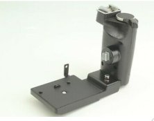
Electrical connections for homemade Bronica Grip

Couples

A
Couples

  • 1
  • 0
  • 44
Exhibition Card

A
Exhibition Card

  • 2
  • 0
  • 76
Flying Lady

A
Flying Lady

  • 6
  • 1
  • 97
Wren

D
Wren

  • 2
  • 0
  • 56

Recent Classifieds

Forum statistics

Threads
199,040
Messages
2,785,194
Members
99,788
Latest member
Rutomu
Recent bookmarks
0
Joined
Dec 28, 2020
Messages
6
Location
Québec
Format
Medium Format
Hello everyone,

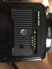
As someone who likes to play with CNCs and 3D printers, I’m taking on the challenge of building a custom grip for my Bronica SQ-Ai. My only challenge, however, is to figure out the electrical connectors under the camera. Does any of you have an insights? Which one triggers the shutter?

unnamed.jpg
 

ic-racer

Member
Joined
Feb 25, 2007
Messages
16,553
Location
USA
Format
Multi Format
Be careful. I was working on a project in the 1980s whereby I needed to trigger my Rollei SL2000F through the electronic release port with a home-made trigger device. I got the pins wrong and connecting two of the wrong pins together fried something, permanently damaging the camera. Instant doorstop.
 

Luckless

Member
Joined
Feb 9, 2016
Messages
1,362
Location
Canada
Format
Multi Format
Between

https://galerie-photo.com/manuels/bronica_sq_ai_instructions.pdf label on page 6 as just 'motor drive contacts'

and

https://www.camleyphotographic.com/shop/bronica-sq-ai-speed-grip-s-condition-4e-5540/ showing an apparent lack of any electrical contacts in the same area

[and without finding a clear pinout or wiring schematic of the camera], the closest I've been able to find is 'potentially none'?

However it does suggest a non-electrical based triggering option may be practical, and that option avoids the risk of poking around the pins manually that IC-Racer pointed out. So that may be an avenue to consider if no one comes along with pinout details for you on this thread.

Testing continuity off an actual motor drive [which looks like it might trigger the shutter electronically through that connector] is probably the safest bet, but I'm guessing you're trying to build your own in part because you don't have one...


If you haven't already, dig around for copies of the service manual [rather than user manual] - While it might not directly give you what you need, it might show enough to make informed guesses without having to poke at the pins blindly or disassemble the camera to trace things visually.

Part of it also comes down to how critical do you consider your current camera body, and how much tinkering you're comfortable doing. [The smell of burned electronics can be a helpful learning experience, but ideally not on stuff you can't easily replace or repair.]
 

wiltw

Subscriber
Joined
Oct 4, 2008
Messages
6,455
Location
SF Bay area
Format
Multi Format
At least on the ETR, the shutter release in the grip is a mechanical pin that thrusts outward from a grip when the shutter release is pressed, not an electronic one! There are three electrical contacts, both on the manual winder grip and on the motor winder grip and on the motor drive grip. I do not know what function is possessed by the three electrical contacts.
 
OP
OP
Joined
Dec 28, 2020
Messages
6
Location
Québec
Format
Medium Format
I’ve been able to 3D print a modified battery holder to tap onto the contacts in the battery compartment. I tried using a homemade 6v battery pack and the camera works like a charm. Now I’d like to hide those 4 AAA batteries in a homemade grip but I’d also like to trigger the camera from it. Perhaps I’ll have to engineer a mechanical lever like on the speed grip. EDEE5571-A610-496C-944A-8B757AFE0F3A.jpeg
 
Photrio.com contains affiliate links to products. We may receive a commission for purchases made through these links.
To read our full affiliate disclosure statement please click Here.

PHOTRIO PARTNERS EQUALLY FUNDING OUR COMMUNITY:


Ilford ADOX Freestyle Photographic Stearman Press Weldon Color Lab Blue Moon Camera & Machine
Top Bottom