


Hello everyone,
While I'm waiting for the crowdfunding campaign for my darkroom timer project to reach its completion (7 days to go), I've been busy with a few other projects. One of them you'll find here in this thread: an LED conversion to my friend's Durst Laborator 1200 enlarger.
Advantages of having a LED head:
+Reliable light source with low power consumption.
+With the right LEDs, no red filter will be necessary under the lens.
+With the right LEDs, no filters will be necessary for multigrade or split grade printing.
+It's possible to build a large enough diffuser and convert a small format enlarger into a large format one.
Everything is still a work in progress and everything you see is mostly a result of our quick and dirty workflow with a shameless amount of hot glue to fix everything down temporarily. We've expected to have a few issues here and there and everything has to be easily reversible until we're more confident in our solutions.
I'll start by posting the where we ended up in the end:

Yes, that's a filled 5L bottle on top of the enlarger. The color head that we've removed weighs even more than that and until the laser-cut-form-fitting-counter-weight arrives, that bottle will have to act as dead weight to prevent the head from breaking free of its locked position and launch into the orbit.
Here's the old CLS 501 color head:

It was in working condition and has no missing parts. Up for sale, if anyone is interested. Make us an offer .
.
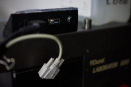
All the drivers for the LEDs, power supply for the control unit and relays are inside the remaining chassis, tucker away behind the faceplate. We 3D printed a bracket (in the wrong orientation so the power switch is away from us while the power cable is near, measure twice print once everyone) and placed it temporarily on top of the head.

Since then, we've reprinted the bracket and everything looks better now (with much less hot glue everywhere) but haven't taken photos of that yet, so this'll have to do. We went for the DSub 9 socket so we have enough pins for communication and other features and it's actually compatible with MAYA (even though we haven't introduced the two of them yet).

The black rectangular box underneath the faceplate is the diffuser box and some of you may have spotted that it says 24x36 mm on it. That's because this enlarger (that my friend had rescued from being scrapped) came with a 35 mm diffuser only. All that bulk and weight for that?

Much better now. If you think that this diffuser is larger than 35 mm, that's because we took a Dremel and cut out most of the bottom section. The newly inserted opaque white acrylic sheet is large enough to cover a 4x5 negative in either direction now.

Four clusters of LEDs. Following the suggestion of our dear friend Alexander Kharlamov (who has already built 6 of these conversion so far), we went for Red, Green and Purple LEDs, placed in the corners. According to some computer simulations, this layout gave us the best, the most even illumination. The ones closest to the center are the red LEDs since even illumination is not a major concern with them. They are there just to act as a safelight, essential when placing some paper underneath the enlarger. That's right, we won't have to use a red safety filter under the lens anymore (we did test them with some paper and they turned out quite safe to use).

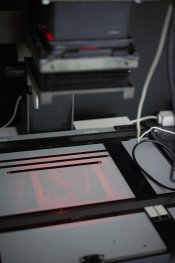
Here's how the diffuser looks like with the red LEDs on. We also covered the inside of the box with some white reflective material and used two layers of opaque white acrylic at the bottom with a 1cm spacer between them. In the end, the lighting seems quite even, even for the red.

The green LEDs are closer to the corners (one in each) and are used for low contrast printing. They are more or less equal to an Ilford #00 filter and only activate the low contrast emulsion of the paper.

Here are the purple LEDs in action. These are also placed close to the corners (each cluster you saw above has RG and P LEDs, one of each). Some guides on the web suggest that Royal Blue LEDs would've been enough to activate the high contrast emulsion only but after digging through some datasheets (and also once again according to Alexander), the peak wavelength needs to be under 420nm to activate the high contrast emulsions of most papers and Royal Blue peaks at 440nm. These are 410nm near-UV LEDs. We also used a 1W driver for four of these while the two colors have 3W drivers of their own. This is because you don't need as much light to activate the much more sensitive high contrast emulsions.

Here's all of them on at the same time. Looks a bit bluish due to the white balance but it's much closer to white in real life.

There's a huge heatsink directly behind the LEDs. We used thermal paste and a drop of epoxy to attach the RGP clusters that are built into circular aluminium PCBs. If we're not happy with the light distribution, we'll look more carefuly into the arrangement and the number of the LEDs but this should be a good starting point.

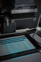
We did not have a 4x5 negative at the point so this is a 6x6 negative. It is bright enough to be seen even with the room lights on.

The purple LEDs can be a bit hard on the eyes so while I took this shot with them, we actually turn the red LEDs on at the same time, resulting in a much more pleasing magenta illumination.

One of these is made with an Ilford #5 filter while the other is made with the LEDs. Can you tell which is which?

One of the first prints we've done.
It was quite a pleasant workflow once everything was put together. I actually built a custom timer for this (using an Arduino Uno we had around) but if we had three light switches mounted on a surface somewhere, this could've been used with a standard timer as well. I'll update the thread with the custom timer and with MAYA in a week or so.
Here are a few footnotes:
-The 3W drivers we used for the Red and Green have a slight delay at the start. I could've just added a fixed number into the code to compensate for the delay but as it turns out, it's not a constant amount. It's around 200ms if they've been turned off for a few minutes and almost instantaneous when doing a test strip. So, we'll either upgrade our drivers, use a different kind (that would also allow dimming) or build a probe inside the head to watch for the changes in light (I'm working on one anyway, because I'll offer that option with MAYA for people who have cold light heads).
-The exposure times are around 5-10 seconds at f/11, which may be a bit too short to be practical, especially for dodging and burning. We'll either add a few more layers of acrylic inside the diffuser box along with some ND filters to dim the light a bit or switch to a dimmable driver.
-We've used a Pentax Spot meter to measure the illumination and everything seems to be within half a stop. However, the prototype spot analyser (accessory for MAYA, coming up soon) tells us that it might be more than what we'd rather have. Will do more experiments to see if we need to increase the quality of the diffusor box.
-We made all the preperations to add a 80mm or 120mm fan on top of the heatsink but surprisingly, we never encountered much heating even after turning everything on for a few minutes. We'll check again using a thermometer inside the light box and quite probably add the fan just in case but so far, everything's been quite cool.
All in all, I've quite enjoyed working with the LED light source. Along with the custom built timer, there is simply no need for any filters. Press the focus button and only the red LEDs are on. Press another button and everything turns on, so you can focus easily. It is so bright that I never needed to open the aperture while working. The exposure times are kept separately for each of the high and low contrast channels and we've even come up with a method to do both exposures automatically, so all that is needed to make the final exposure after the initial test strips is a single button press.
It is theoretically possible to set it up for single grade printing between #00 and #5 but so far we've only used it for split grade printing. Will experiment with different methods and techniques in the near future.
Next up, I'll be modifying my Kaiser 6002. Might even build and offer conversion kits for Kaiser V-Series enlargers since all of them have compatible parts, so it should be possible to build a one-size-fits-all solution for them. Then you may expect a guide and maybe even a conversion kit for Durst M805.
And then finally a complete, built from scratch enlarger project sometime later this year.
I'm open to all questions, comments and ideas so please, don't hold anything back.
While I'm waiting for the crowdfunding campaign for my darkroom timer project to reach its completion (7 days to go), I've been busy with a few other projects. One of them you'll find here in this thread: an LED conversion to my friend's Durst Laborator 1200 enlarger.
Advantages of having a LED head:
+Reliable light source with low power consumption.
+With the right LEDs, no red filter will be necessary under the lens.
+With the right LEDs, no filters will be necessary for multigrade or split grade printing.
+It's possible to build a large enough diffuser and convert a small format enlarger into a large format one.
Everything is still a work in progress and everything you see is mostly a result of our quick and dirty workflow with a shameless amount of hot glue to fix everything down temporarily. We've expected to have a few issues here and there and everything has to be easily reversible until we're more confident in our solutions.
I'll start by posting the where we ended up in the end:
Yes, that's a filled 5L bottle on top of the enlarger. The color head that we've removed weighs even more than that and until the laser-cut-form-fitting-counter-weight arrives, that bottle will have to act as dead weight to prevent the head from breaking free of its locked position and launch into the orbit.
Here's the old CLS 501 color head:
It was in working condition and has no missing parts. Up for sale, if anyone is interested. Make us an offer
.All the drivers for the LEDs, power supply for the control unit and relays are inside the remaining chassis, tucker away behind the faceplate. We 3D printed a bracket (in the wrong orientation so the power switch is away from us while the power cable is near, measure twice print once everyone) and placed it temporarily on top of the head.
Since then, we've reprinted the bracket and everything looks better now (with much less hot glue everywhere) but haven't taken photos of that yet, so this'll have to do. We went for the DSub 9 socket so we have enough pins for communication and other features and it's actually compatible with MAYA (even though we haven't introduced the two of them yet).
The black rectangular box underneath the faceplate is the diffuser box and some of you may have spotted that it says 24x36 mm on it. That's because this enlarger (that my friend had rescued from being scrapped) came with a 35 mm diffuser only. All that bulk and weight for that?
Much better now. If you think that this diffuser is larger than 35 mm, that's because we took a Dremel and cut out most of the bottom section. The newly inserted opaque white acrylic sheet is large enough to cover a 4x5 negative in either direction now.
Four clusters of LEDs. Following the suggestion of our dear friend Alexander Kharlamov (who has already built 6 of these conversion so far), we went for Red, Green and Purple LEDs, placed in the corners. According to some computer simulations, this layout gave us the best, the most even illumination. The ones closest to the center are the red LEDs since even illumination is not a major concern with them. They are there just to act as a safelight, essential when placing some paper underneath the enlarger. That's right, we won't have to use a red safety filter under the lens anymore (we did test them with some paper and they turned out quite safe to use).
Here's how the diffuser looks like with the red LEDs on. We also covered the inside of the box with some white reflective material and used two layers of opaque white acrylic at the bottom with a 1cm spacer between them. In the end, the lighting seems quite even, even for the red.
The green LEDs are closer to the corners (one in each) and are used for low contrast printing. They are more or less equal to an Ilford #00 filter and only activate the low contrast emulsion of the paper.
Here are the purple LEDs in action. These are also placed close to the corners (each cluster you saw above has RG and P LEDs, one of each). Some guides on the web suggest that Royal Blue LEDs would've been enough to activate the high contrast emulsion only but after digging through some datasheets (and also once again according to Alexander), the peak wavelength needs to be under 420nm to activate the high contrast emulsions of most papers and Royal Blue peaks at 440nm. These are 410nm near-UV LEDs. We also used a 1W driver for four of these while the two colors have 3W drivers of their own. This is because you don't need as much light to activate the much more sensitive high contrast emulsions.
Here's all of them on at the same time. Looks a bit bluish due to the white balance but it's much closer to white in real life.
There's a huge heatsink directly behind the LEDs. We used thermal paste and a drop of epoxy to attach the RGP clusters that are built into circular aluminium PCBs. If we're not happy with the light distribution, we'll look more carefuly into the arrangement and the number of the LEDs but this should be a good starting point.
We did not have a 4x5 negative at the point so this is a 6x6 negative. It is bright enough to be seen even with the room lights on.
The purple LEDs can be a bit hard on the eyes so while I took this shot with them, we actually turn the red LEDs on at the same time, resulting in a much more pleasing magenta illumination.
One of these is made with an Ilford #5 filter while the other is made with the LEDs. Can you tell which is which?
One of the first prints we've done.
It was quite a pleasant workflow once everything was put together. I actually built a custom timer for this (using an Arduino Uno we had around) but if we had three light switches mounted on a surface somewhere, this could've been used with a standard timer as well. I'll update the thread with the custom timer and with MAYA in a week or so.
Here are a few footnotes:
-The 3W drivers we used for the Red and Green have a slight delay at the start. I could've just added a fixed number into the code to compensate for the delay but as it turns out, it's not a constant amount. It's around 200ms if they've been turned off for a few minutes and almost instantaneous when doing a test strip. So, we'll either upgrade our drivers, use a different kind (that would also allow dimming) or build a probe inside the head to watch for the changes in light (I'm working on one anyway, because I'll offer that option with MAYA for people who have cold light heads).
-The exposure times are around 5-10 seconds at f/11, which may be a bit too short to be practical, especially for dodging and burning. We'll either add a few more layers of acrylic inside the diffuser box along with some ND filters to dim the light a bit or switch to a dimmable driver.
-We've used a Pentax Spot meter to measure the illumination and everything seems to be within half a stop. However, the prototype spot analyser (accessory for MAYA, coming up soon) tells us that it might be more than what we'd rather have. Will do more experiments to see if we need to increase the quality of the diffusor box.
-We made all the preperations to add a 80mm or 120mm fan on top of the heatsink but surprisingly, we never encountered much heating even after turning everything on for a few minutes. We'll check again using a thermometer inside the light box and quite probably add the fan just in case but so far, everything's been quite cool.
All in all, I've quite enjoyed working with the LED light source. Along with the custom built timer, there is simply no need for any filters. Press the focus button and only the red LEDs are on. Press another button and everything turns on, so you can focus easily. It is so bright that I never needed to open the aperture while working. The exposure times are kept separately for each of the high and low contrast channels and we've even come up with a method to do both exposures automatically, so all that is needed to make the final exposure after the initial test strips is a single button press.
It is theoretically possible to set it up for single grade printing between #00 and #5 but so far we've only used it for split grade printing. Will experiment with different methods and techniques in the near future.
Next up, I'll be modifying my Kaiser 6002. Might even build and offer conversion kits for Kaiser V-Series enlargers since all of them have compatible parts, so it should be possible to build a one-size-fits-all solution for them. Then you may expect a guide and maybe even a conversion kit for Durst M805.
And then finally a complete, built from scratch enlarger project sometime later this year.
I'm open to all questions, comments and ideas so please, don't hold anything back.
Attachments
Last edited:


