Does anybody have a schematics for Compur Electronic shutters ?

Dog Opposites

A
Dog Opposites

  • 1
  • 1
  • 88
Acrobatics in the Vondelpark

A
Acrobatics in the Vondelpark

  • 6
  • 3
  • 158
Finn Slough Fishing Net

A
Finn Slough Fishing Net

  • 1
  • 0
  • 97
Dried roses

A
Dried roses

  • 13
  • 7
  • 181
Hot Rod

A
Hot Rod

  • 5
  • 0
  • 111

Recent Classifieds

Forum statistics

Threads
197,463
Messages
2,759,447
Members
99,512
Latest member
vincent83
Recent bookmarks
0

GeorgesGiralt

Member
Joined
Sep 16, 2004
Messages
525
Location
Toulouse, Fr
Format
Large Format
Hi !
Everything is into the title.
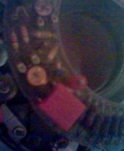
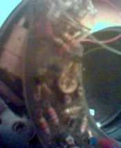
I've got a nice Compur Electronic size #1 with the slowest setting (32 seconds) not working. Blades open but do not close, even after 10 minutes.
I've a maintenance manual copy but the electronics is described as a single part. As Mr Compur does not answer the phone anymore ,-) , I'm looking for a schematic to fix it.
Any leads or help will be greatly appreciated !
TIA
 
OP
OP

GeorgesGiralt

Member
Joined
Sep 16, 2004
Messages
525
Location
Toulouse, Fr
Format
Large Format
Hi Curt !
This is the user manual.
I'm looking for the schematics of the electronic part which is NOT in the maintenance manual...
Thanks anyway for your help !
 

Struan Gray

Member
Joined
Nov 5, 2004
Messages
914
Location
Lund, Sweden
Format
Multi Format
I'm pretty sure the smaller sized electronic compurs just bleed a capacitor through various resistors to set the timing. If the other speeds work properly I would open it up and look for a broken lead or dud connection to one leg of a resistor array.
 

DWThomas

Subscriber
Joined
Jun 13, 2006
Messages
4,601
Location
SE Pennsylvania
Format
Multi Format
smaller sized electronic compurs just bleed a capacitor through various resistors to set the timing.
If they use RC timing and the shutter is old, the problem may be increased leakage current in the capacitor. In such a case the higher resistance used to get longer time constants can be swamped by the capacitor leakage. I had this problem with an RC-controlled enlarger timer and fixed it by replacing the capacitor with a newly purchased solid tantalum part.

My 2¢ (2 microfarads?)

DaveT
 
OP
OP

GeorgesGiralt

Member
Joined
Sep 16, 2004
Messages
525
Location
Toulouse, Fr
Format
Large Format
Hi !
THe situation has worsened here as none of the timed speeds work anymore. (I'm left with the 1/500 second).
The electronics comprise 6 transistors (in very small packages with golden leads, pre- SMC components) which of course have no markings, so I'm stuck with a dead circuit, no schematic, no clues and no luck....
Of course the electronic purpose is to provide a delay when blade open before they are shut. This is provided by the charging (or discharging) of a capacitor (there is only one onto the board) and the command is made throug a coil magnetically holding the closing shutter lever. When the coil gets de-ergized, the blades close. 3 switches control power for the circuit and functionning (one is actuated by the shtter trigger, one by the mechanism and the last one by the blade control lever) so without the schematics it is quite difficult to find what the timing is, where the problem is and how to cure it.
Anyway, thanks for your help !
 

Struan Gray

Member
Joined
Nov 5, 2004
Messages
914
Location
Lund, Sweden
Format
Multi Format
One clue is that the circuit works properly at a wide range of supply voltages. I ran my No. 1 electronic on a lab power supply at voltages between 3 V and, I think, 6V with no appreciable change in the timing. (I was looking to see if using a CR2 battery would work, since they fit nicely into the compartment with a foil spacer). To me, that says the timing is RC and the transistors are there for control and switching, and perhaps to make a flip-flop signifying the shutter open/closed state.

Only firing at 1/500 is what happens when there is no battery at all. Perhaps the solution is simple :smile:

Seriously, the prongs to which the battery compartment attaches and the contacts within the compartment are very, very prone to corrosion. I would check that you are getting juice to the circuit before looking for anything more complicated. Forgive me if I am teaching you how to suck eggs...
 
Last edited by a moderator:
OP
OP

GeorgesGiralt

Member
Joined
Sep 16, 2004
Messages
525
Location
Toulouse, Fr
Format
Large Format
Struan,
Thank you, I'll check this...
Believe me, I was so dispointed it stop working that I forgot to check that the battery voltage goes where it should.
Thanks !
BTW, the maint. maual state it should run between 2.5 and 6 V ... It was designed for a 5.6 V mercury battery and next changed for a PX21 4.5 V
 
OP
OP

GeorgesGiralt

Member
Joined
Sep 16, 2004
Messages
525
Location
Toulouse, Fr
Format
Large Format
Struan,
Nice try.
Same with a new 4.5 V battery and powering the electronic right at the right place with two soldered wires...
Bad luck.
 

PHOTOTONE

Member
Joined
Oct 30, 2006
Messages
2,412
Location
Van Buren, A
Format
Large Format
It is most probably the single capacitor you saw. Capacitors do not have an extremely long life, as compared to the other electronic components in a circuit. I have made a lot of older electronic items work just fine, but just replacing all the capacitors. If this were my shutter, I would replace the capacitor, then decide. As capacitors age they drift far from marked value thus upsetting the circuit parameters. They also start leaking DC current.
 
OP
OP

GeorgesGiralt

Member
Joined
Sep 16, 2004
Messages
525
Location
Toulouse, Fr
Format
Large Format
Hi !
I've de-soldered one capacitor, and put one of same value (not same technoligy, as this was unavaillable) but, it still does not work.
As nobody seems to have a schematics, does anyone have a clue on how to know what kind of transistors are in ?
 

Struan Gray

Member
Joined
Nov 5, 2004
Messages
914
Location
Lund, Sweden
Format
Multi Format
George, sorry things are not working for you. I am inspired by your persistence.

Transistors in the little metal cans should have a name on the top of the can, but not all do, especially the more commodity-type common ones. In your situation I would look for a grizzled electronics technician and ask him to make a best guess.

Alternately, take some digisnaps and post them here, I'm sure some of the more electronically-gifted among us can help at least narrow the search.

Alternately(2): start looking for another Compur Electronic 1. They turn up regularly on eBay.de, and are cheap even in good working order. You can swap the aperture scales and lens cells to the working shutter and discard the rest.
 

AgX

Member
Joined
Apr 5, 2007
Messages
29,990
Location
Germany
Format
Multi Format
I think Struan's first idea is a good one. If you know an electronics technician experienced with electronics of the sixties/seventies, ask him. It should be a simple circuit, he should be able to give you a hint.
 

AgX

Member
Joined
Apr 5, 2007
Messages
29,990
Location
Germany
Format
Multi Format
Georges,

I just phoned the Prontor company who took over most of the Deckel company production when they were slowly closing down central shutter production. Of course the Prontor company is busy on different fields now too...
I spoke to a kind engineer, who did not even see these shutters any more, nor is there anybody left who did. But he looked into his files:
Definitely no circuit diagrams of the Compur electronic #1 and #3 shutters filed any longer. He too took the view that a technician described as above should be able to solve the problem.
 
OP
OP

GeorgesGiralt

Member
Joined
Sep 16, 2004
Messages
525
Location
Toulouse, Fr
Format
Large Format
Hi guys,
Unfortunately, even if I studied electronics in my young days, I'm stuck. Since I did not practice since college, it is quite normal.
This device is pre-SMC so transistors are in their mini packages with only a color paint on top to differentiate them during production. I can tell they are military grade because the leads are gold plated.
My big problem is the lack of proper instruments. I can't tell if the circuit energize the coil because I've no "sample and hold" voltmeter. And my old Tektronics scope serve nothing too.
Last but not least, I can't remember the type of circuitry one would use before the advent of 555 timer chip. And it is difficult to find a timer schematics without 555 circuit now.
As for finding a size one on Ebay, I've done that. It worked about 10 times flawlessly and is now dead. Maybe a nasty virus in my room ? ;-)
 

AgX

Member
Joined
Apr 5, 2007
Messages
29,990
Location
Germany
Format
Multi Format
Georges,

As Struan already said, those early electronically controlled shutters in principle are only based on a capacitor being drained via a resistor to power an electromecanical device holding the shutter blades open. If the current coming out of that capacitator stops, the shutter closes.
Thus you have one capacitator of well chosen capacity, a loading source (of well chosen voltage?), and a resistor of well chosen resistance. When the shutter is released a spring opens the shutter, at that moment the loading source is taken off and the same time another circuit is closed to uncharge the capacitator via that resistor and that electromechanical device (a coil) which is somehow holding the blades open. The exposure time is controlled by the values of loading voltage, capacity and the resistance of that resistor and that coil (might even by that inner resistance of the capacitator too…). To change times one has to put another resistor ( or even another capacitor) into the circuit.
That’s all. Those transistors could be used to control the voltage coming from the battery or to steer that electromechanical device.

Still, to my understanding a true mechanical fault cannot be excluded.


I don’t see how we could help you any further via the net.
 

Struan Gray

Member
Joined
Nov 5, 2004
Messages
914
Location
Lund, Sweden
Format
Multi Format
Just in case you don't know (and for the benefit of lurkers) you might want to buy - or, better, borrow - a transistor tester. Just plug in the can and it will tell you if the transistor is blown or not. The better ones will automatically tell you if you have an NPN or PNP model, and a lot else besides, but even the cheapie versions save a lot of time over hooking the transistor up to two power supplies and measuring the current characteristic.
 

ben-s

Member
Joined
Jul 12, 2006
Messages
444
Location
Nottingham,
Format
Multi Format
Just in case you don't know (and for the benefit of lurkers) you might want to buy - or, better, borrow - a transistor tester. Just plug in the can and it will tell you if the transistor is blown or not. The better ones will automatically tell you if you have an NPN or PNP model, and a lot else besides, but even the cheapie versions save a lot of time over hooking the transistor up to two power supplies and measuring the current characteristic.

I'll second that. I can recommend the Peak Atlas DCA55:
http://www.peakelec.co.uk/acatalog/jz_dca55.html
This one is very cheap, tells you pretty much all you need to know, and works for diodes and transistors.

It's fantastic for working with "junk box" or unknown components, as it also tells you the pinout, which saves much searching for datasheets.


Peak make other models for testing:
Capacitors, inductors and resistors (Atlas LCR)
ESR and capacitance (Atlas ESR)
Thyristors and Triacs (Atlas SCR)
 

ben-s

Member
Joined
Jul 12, 2006
Messages
444
Location
Nottingham,
Format
Multi Format
Hmmm... Having done some googling, I found this:
Electronic control device for photographic exposure factors

It's a Compur patent, and the method of operation would seem to tally up with the semiconductors Georges has found in the shutter.

In this case, It could well be a dirty potentiometer causing the problem.

Georges, have any of the semiconductors got more than 3 legs? - I'm thinking that one might be an op-amp in a TO3 style case.
 

AgX

Member
Joined
Apr 5, 2007
Messages
29,990
Location
Germany
Format
Multi Format
I guess! that patent lies behind the two Prontor 500 electronic shutters.

Anyway, a photo of the intestine of Georges' shutter could be helpful to the others (I can't look at photos at APUG).
 
OP
OP

GeorgesGiralt

Member
Joined
Sep 16, 2004
Messages
525
Location
Toulouse, Fr
Format
Large Format
Hmmm... Having done some googling, I found this:
Electronic control device for photographic exposure factors

It's a Compur patent, and the method of operation would seem to tally up with the semiconductors Georges has found in the shutter.

In this case, It could well be a dirty potentiometer causing the problem.

Georges, have any of the semiconductors got more than 3 legs? - I'm thinking that one might be an op-amp in a TO3 style case.
Hi !
Great !
The Compur Patent is the better guess at a schematics I've seen for a while.
The Compur size 1 only has transistors (5 pieces) but the Compur size 3 has a couple of transistors and an IC in a TO3 package. Maybe an OP amp. (As the size 3 is working fine, I won't open it for a while ....)
I'll read all the patent literature and try to figure out a schematics or a repair strategy.
 

ben-s

Member
Joined
Jul 12, 2006
Messages
444
Location
Nottingham,
Format
Multi Format
If you take any photos, of the insides of the shutter, I'd be interested to see them.
Let us know how you get on with fixing it.
 
OP
OP

GeorgesGiralt

Member
Joined
Sep 16, 2004
Messages
525
Location
Toulouse, Fr
Format
Large Format
Well, the only d*** camera I own is my GSM phone. And it only makes 640x480 pix photos (and this mode is called "Hi Res" ! ) so I wonder if you will be glad ;-)
I'll do that tomorrow before sending them to a repairman for a cotation ....
 
OP
OP

GeorgesGiralt

Member
Joined
Sep 16, 2004
Messages
525
Location
Toulouse, Fr
Format
Large Format
The pictures you requested.

So, I managed to get some picts.
They are very poor !
The first one shows the circuit board in place. The golden patches are the contacts onto which the speed setting brush touch.
The second one shows the part of the circuit board where the electronics is, and the coil used to control the shutter blades. (The coil is not genuine, on my other shutter it has a small label with a part number on it and look netter)
The next picture show the board removed. On top are the speed controlling resistors, one per speed. The red square box is the main capacitor, left to it, the red circle is one retaining screw with its washer.Just under the red capacitor is one adjustable resistor, gold plated, and a little down, and left another one, this one not plated.
Next pict shows "in more detail" the resistors used for speed control. They are mainly 2% tolerance. Next pict is a "close-up" of the capacitor, adjustable resistor.
And on last pict, you see the other adjustable resistor, with one transistor (left) with its minimal packaging and it's gold plated contacts.
 

Attachments

  • Machin(21).jpg
    Machin(21).jpg
    16.2 KB · Views: 312
  • Machin(22).jpg
    Machin(22).jpg
    15.8 KB · Views: 325
  • Machin(27).jpg
    Machin(27).jpg
    17.7 KB · Views: 341
  • Machin(28).jpg
    Machin(28).jpg
    13.1 KB · Views: 299
  • Machin(29).jpg
    Machin(29).jpg
    18 KB · Views: 292
  • Machin(30).jpg
    Machin(30).jpg
    15.4 KB · Views: 369
Photrio.com contains affiliate links to products. We may receive a commission for purchases made through these links.
To read our full affiliate disclosure statement please click Here.

PHOTRIO PARTNERS EQUALLY FUNDING OUR COMMUNITY:


Ilford ADOX Freestyle Photographic Stearman Press Weldon Color Lab Blue Moon Camera & Machine
Top Bottom