Carbonista! What percent dichromate for Carbon from digi-negs?

Signs & fragments

A
Signs & fragments

  • 1
  • 0
  • 10
Summer corn, summer storm

D
Summer corn, summer storm

  • 1
  • 1
  • 23
Horizon, summer rain

D
Horizon, summer rain

  • 0
  • 0
  • 29
$12.66

A
$12.66

  • 6
  • 5
  • 167
A street portrait

A
A street portrait

  • 1
  • 0
  • 163

Recent Classifieds

Forum statistics

Threads
198,814
Messages
2,781,231
Members
99,712
Latest member
asalazarphoto
Recent bookmarks
0

R Shaffer

Member
Joined
May 9, 2007
Messages
436
Location
Santa Cruz,
Format
Multi Format
Ciao All,

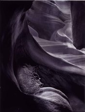
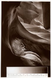
I've decided to print my Antelope Canyon series in carbon and the early results are very promising.

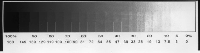
I am curious as to what percent dichromate you Carbonista's use for your digi-negs? I have created my initial curve using a 2% Amm. Dichromate. I used a relatively low percent so I would not need a very high DR in the negatives. Hoping to avoid railroad tracks.

However, I'm thinking now that with that low a dichromate it is difficult to get consistent midtone separation.

Any opinions?
 

Attachments

  • carbon-#2007.jpg
    carbon-#2007.jpg
    96.4 KB · Views: 151

gmikol

Subscriber
Joined
Mar 2, 2009
Messages
633
Location
Vancouver, W
Format
35mm
Rob--

I've been using 2% potassium dichromate for my stuff. I've had the same concerns that you do...not so much in terms of mid-tones per se, but in the possibility of enhancing "grain" from the digi-negs. In practice, I really haven't seen it, but I've printed some fairly busy images...no smooth tonal areas like skies.

My ink limits are 40PK / 35Y. The next thing I want to try is a PK / Y / C curve. I've seen some data that suggests that the C ink has almost as much UV density as Y, and that would give a curve that had a 3-part curve (black), a 2-part curve (C), and a 1-part curve (Y). I think this would give a good distribution of different dithering patterns, which (I hope) would minimize grain.

My carbon stuff has been set aside for a few months, once I get back up and running, I'll probably play around with higher percentages to see if it makes much of a difference (but can't get much higher than about 5 or 6% with potassium dichromate...the acetone tends to knock the dichromate out of solution).

Good luck--

Greg
 
OP
OP

R Shaffer

Member
Joined
May 9, 2007
Messages
436
Location
Santa Cruz,
Format
Multi Format
That follows pretty close to my own experience so far. My curve is also 40pK, but then 15Y & 5C. My last print did not show very definitive steps between say 40 & 70%, it clearly gets darker, but in a mushy sort of way.

I'm not too worried about the dither pattern, its there, but not at all intrusive.

I'm kinda thinking that the differences in the amount of ink laid down is so minimal between say 40% & 50%, that minor inconsistencies in the tissue thickness or sensitivity are having a greater impact on final density. Does that make any sense?

So I will try again at 4% Amm. Dichromate and see how that goes.
 

pschwart

Subscriber
Joined
Jul 15, 2005
Messages
1,147
Location
San Francisco, CA
Format
Multi Format
Ciao All,
However, I'm thinking now that with that low a dichromate it is difficult to get consistent midtone separation.
This is not my experience. You may need to tweak other parameters like pigment concentration, negative density, or the correction curve.
 
Last edited by a moderator:

gmikol

Subscriber
Joined
Mar 2, 2009
Messages
633
Location
Vancouver, W
Format
35mm
However, I'm thinking now that with that low a dichromate it is difficult to get consistent midtone separation.

I'm reminded of another point I wanted to make...

If one assumes that you're consistent in your working methods (composition of tissue, sensitizing, drying, printing times, etc.), then the linearization process will ensure you get the midtone separation.

I am surprised you're using that much less ink than I am, given our parameters are similar in other ways, and that you're saying your midtones weren't distinct. My experience was that I had to tame the midtone contrast while boosting the low and high ends with a curve in QTR.

--Greg
 
OP
OP

R Shaffer

Member
Joined
May 9, 2007
Messages
436
Location
Santa Cruz,
Format
Multi Format
This is not my experience. You may need to tweak other parameters like pigment concentration, negative density, or the correction curve.

This is true. If I increase the pigment concentration it will increase the contrast as well. I am, as I understand it, at about the middle of the scale with 10g/L
 
OP
OP

R Shaffer

Member
Joined
May 9, 2007
Messages
436
Location
Santa Cruz,
Format
Multi Format
I'm reminded of another point I wanted to make...

If one assumes that you're consistent in your working methods (composition of tissue, sensitizing, drying, printing times, etc.), then the linearization process will ensure you get the midtone separation.

I am surprised you're using that much less ink than I am, given our parameters are similar in other ways, and that you're saying your midtones weren't distinct. My experience was that I had to tame the midtone contrast while boosting the low and high ends with a curve in QTR.

--Greg

I have attached a scan of my last step wedge. I include a step wedge at the base of the print and this came from the print I included with the initial post. I really hate just printing test strips.

The steps really don't appear to be very distinct. When I measure it in photoshop I get a reading of 56 @ 40% and 80 @ 70%, so I have overexposed this some. I did this because the previous print was underexposed with just barely a hint of tone @ 30%.

So not only am I using less ink, BUT I'm having to overexpose it to burn thru the less ink. Perhaps having the step wedge at the bottom is a mistake since my tissues are more consistent in the middle and I may be getting more sensitizer in the middle.
 

Attachments

  • Carbon-R4.jpg
    Carbon-R4.jpg
    42.3 KB · Views: 126

pschwart

Subscriber
Joined
Jul 15, 2005
Messages
1,147
Location
San Francisco, CA
Format
Multi Format
so I have overexposed this some. I did this because the previous print was underexposed with just barely a hint of tone @ 30%.

So not only am I using less ink, BUT I'm having to overexpose it to burn thru the less ink
I'd suggest determining your base exposure, then using this consistently to derive the correction curve.

Concerning "overexposing" to burn through the ink: don't forget that everything else being equal, the UV blocking is determined by the pigment concentration PLUS the thickness of the tissue. A .5% pigment concentration poured to a wet height of 2mm will provide the same UV blocking as a 1% concentration poured to a wet height of 1mm.
 
OP
OP

R Shaffer

Member
Joined
May 9, 2007
Messages
436
Location
Santa Cruz,
Format
Multi Format
I'd suggest determining your base exposure, then using this consistently to derive the correction curve.

Concerning "overexposing" to burn through the ink: don't forget that everything else being equal, the UV blocking is determined by the pigment concentration PLUS the thickness of the tissue. A .5% pigment concentration poured to a wet height of 2mm will provide the same UV blocking as a 1% concentration poured to a wet height of 1mm.

I figured my base exposure at around 10min and began creating the curve around that exposure. But I went and increased the exposure time to 12min on the third test to try and bring the 50% value closer to 50. I could have reduced the ink density in the negative.

I'm not really sure, but does it make a difference whether you increase exposure or reduce ink load? This would be prior to actually adding a correction curve.

My comment about overexposing was in regards to the negative rather than the tissue. Although I am pouring to a wet height of 1mm.

So I had made new tissues last week with Higgins Non-waterproof ink. The first batch made with Neutral Tint were just too purple, although the color did grow on me. Here is an example of the new tissue.

This one came out quite warm.
 

Attachments

  • WarmCarbon.jpg
    WarmCarbon.jpg
    73.1 KB · Views: 117

gmikol

Subscriber
Joined
Mar 2, 2009
Messages
633
Location
Vancouver, W
Format
35mm
I figured my base exposure at around 10min and began creating the curve around that exposure. But I went and increased the exposure time to 12min on the third test to try and bring the 50% value closer to 50. I could have reduced the ink density in the negative.

I'm not really sure, but does it make a difference whether you increase exposure or reduce ink load? This would be prior to actually adding a correction curve.

I'm surprised you're struggling with this, Rob...You've been printing with digi-negs for a while, no?

If one assumes you've settled on a sensitizer percentage and a tissue composition, you need to adjust exposure to get the DMax you want, then adjust ink limits based on the 0% step (more ink if there's still tone at the 0% step, less ink if the 0% and 5% steps are both paper-white). Then worry about tweaking the curve shape and linearizing.

And there's no reason for the 50% step to be at L*=50. Here's a conceptual example...if your L* for DMax is 10, but your paper is not very white L*=80. Properly linearized, the L* of the 50% step would be more like 45, not 50.

Sounds like you're trying to make a pre-existing profile fit these new tissues.

Regardless...I wish you luck. I kinda like the purplish tint of the first print...

--Greg
 
OP
OP

R Shaffer

Member
Joined
May 9, 2007
Messages
436
Location
Santa Cruz,
Format
Multi Format
I'm surprised you're struggling with this, Rob...You've been printing with digi-negs for a while, no?

If one assumes you've settled on a sensitizer percentage and a tissue composition, you need to adjust exposure to get the DMax you want, then adjust ink limits based on the 0% step (more ink if there's still tone at the 0% step, less ink if the 0% and 5% steps are both paper-white). Then worry about tweaking the curve shape and linearizing.

And there's no reason for the 50% step to be at L*=50. Here's a conceptual example...if your L* for DMax is 10, but your paper is not very white L*=80. Properly linearized, the L* of the 50% step would be more like 45, not 50.

Sounds like you're trying to make a pre-existing profile fit these new tissues.

Regardless...I wish you luck. I kinda like the purplish tint of the first print...

--Greg

No not struggling, just curious how others do this. I use exposure in addition to changing the ink density on the negative. I am not familiar with the L* ( = luminance? ), but it makes clear enough sense.

Using your example Dmax L* = 10 & Paper White L* = 80

So my 20% step has a L*= 80, it should have L*=66 ( too light )
and my 50% step has a L*=52, it should have L*=45 ( too light )

If things look pretty linear on the step wedge, I would probably increase the exposure, rather than reduce the ink limits.

So do you measure your step wedges as Luminance in Lab space?

Anywho... That nice purple is 8gram Neutral Tint water color + 1 gram Scarlet Red to a liter of glop. Just sensitized a new tissue, trying to work towards something more neutral.
 

gmikol

Subscriber
Joined
Mar 2, 2009
Messages
633
Location
Vancouver, W
Format
35mm
Using your example Dmax L* = 10 & Paper White L* = 80

So my 20% step has a L*= 80, it should have L*=66 ( too light )
and my 50% step has a L*=52, it should have L*=45 ( too light )

Well...don't take my numbers as gospel. L*=10 is about D=1.95 (a decent black), but L*=80 is about D=0.25, which would be a fairly muddy-looking paper. Something like FAEW or Platine could have an L* in the 95-98 range. It was just to illustrate my point that the 50% step need not be at L*=50, especially prior to linearization.

If things look pretty linear on the step wedge, I would probably increase the exposure, rather than reduce the ink limits.

But you need to do both. As you increase the exposure, you are not only darkening the shadows, you are darkening your lightest tones as well, perhaps even adding some tone to the 0% step, which should be paper-white. You'd need to then increase ink limits to get back to a paper white.

So do you measure your step wedges as Luminance in Lab space?

I do, but that's because I am more likely to use my i1Pro than a densitometer, and the software I use with the i1Pro (ArgyllCMS) doesn't report density, but does luminance.


--Greg

PS--Rob, I hope you don't find this confrontational or as if I'm talking down to you. I'm trying to write my replies based on your comments in such a way that a wider audience, of varying skill levels, benefits from it.
 

Bob Carnie

Subscriber
Joined
Apr 18, 2004
Messages
7,735
Location
toronto
Format
Med. Format RF
What method are you using to read the L channels?? or what device are you using?
 
OP
OP

R Shaffer

Member
Joined
May 9, 2007
Messages
436
Location
Santa Cruz,
Format
Multi Format
I do, but that's because I am more likely to use my i1Pro than a densitometer, and the software I use with the i1Pro (ArgyllCMS) doesn't report density, but does luminance.


--Greg

PS--Rob, I hope you don't find this confrontational or as if I'm talking down to you. I'm trying to write my replies based on your comments in such a way that a wider audience, of varying skill levels, benefits from it.

Before my last response, I had been referring to using scanner and measuring %K with the eyedropper tool in PS. So my 50% step should be 50%K. I have a densitometer, but I'm mostly too lazy to get it out of the closet and set it up.

Had not thought you were the least bit confrontational. Was I? :wondering:
 

gmikol

Subscriber
Joined
Mar 2, 2009
Messages
633
Location
Vancouver, W
Format
35mm
What method are you using to read the L channels?? or what device are you using?

I'm using an i1Pro spectrophotometer, and the open-source ArgyllCMS software. I use Argyll's "spotread" or "chartread" (depending on how many patches I need to read), and it puts XYZ and Lab into the log file.

And in writing this, I realize that Bob's question may be directed at Rob...so I'll add this. Reading %K in Photoshop is probably not the best choice, since it's not anchored to any visual/perceptual system. You'd probably be better off reading L values from the info palette (you can set it to read out in various color systems).

--Greg
 

gmikol

Subscriber
Joined
Mar 2, 2009
Messages
633
Location
Vancouver, W
Format
35mm
Had not thought you were the least bit confrontational. Was I? :wondering:

Not at all...but I tend to be very matter-of-fact, and on the 'net, matter-of-fact can sometimes come across as a--hole.

And now, back to the topic at hand...

--Greg
 

Bob Carnie

Subscriber
Joined
Apr 18, 2004
Messages
7,735
Location
toronto
Format
Med. Format RF
Hi Greg
The question was directed to you, and thank you for your response.
I too have a xrite I 1 pro and never considered this.
What I would like to do is read L readings independent from PS .
I indeed use the L info pallette as my main source of readings while in PS and have been looking for a way of reading 100step tablets that I generate but on the print and not scanning.
I never heard of Argy11CMS software and will look it up.

its funny the answer to this is right before my eyes and never picked up on it.


thanks

Bob
I'm using an i1Pro spectrophotometer, and the open-source ArgyllCMS software. I use Argyll's "spotread" or "chartread" (depending on how many patches I need to read), and it puts XYZ and Lab into the log file.

And in writing this, I realize that Bob's question may be directed at Rob...so I'll add this. Reading %K in Photoshop is probably not the best choice, since it's not anchored to any visual/perceptual system. You'd probably be better off reading L values from the info palette (you can set it to read out in various color systems).

--Greg
 

John Lockhart

Member
Joined
Nov 17, 2009
Messages
42
Format
35mm
I have been using 5% ammonium dichromate dilluted 1:1 with 90% isopropyl alcohol and I have been printing my negatives on an Epson r1800 using QTR. So, far the results have been very good. I took a workshop with Sandy King and I am using his tissue formulation and thickness. During the workshop we used 6% potassium dichromate 1:1 with acetone. Attached is a photo of one of my initial prints.
 

Attachments

  • Homework.jpg
    Homework.jpg
    250.7 KB · Views: 121
Last edited by a moderator:
Photrio.com contains affiliate links to products. We may receive a commission for purchases made through these links.
To read our full affiliate disclosure statement please click Here.

PHOTRIO PARTNERS EQUALLY FUNDING OUR COMMUNITY:


Ilford ADOX Freestyle Photographic Stearman Press Weldon Color Lab Blue Moon Camera & Machine
Top Bottom