Building Stuart Brown's shutter speed testing - inconsistency at higher speeds?

about to extinct

D
about to extinct

  • 0
  • 0
  • 43
Fantasyland!

D
Fantasyland!

  • 9
  • 2
  • 112
perfect cirkel

D
perfect cirkel

  • 2
  • 1
  • 121
Thomas J Walls cafe.

A
Thomas J Walls cafe.

  • 4
  • 8
  • 292

Recent Classifieds

Forum statistics

Threads
198,746
Messages
2,780,293
Members
99,693
Latest member
lachanalia
Recent bookmarks
0

Dhr Foto

Member
Joined
Jan 2, 2025
Messages
17
Location
The Netherlands
Format
Multi Format
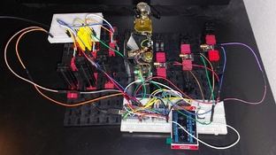
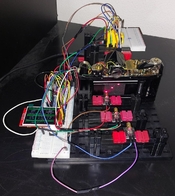
I have built Stuart Brown's shutter speed tester and I'd like to confirm that everything works beautifully. I have included some images where you can see the breadboard prototype mounted to some Fischer Technik (a very European construction toy). It looks like a rat's nest of wires and electronics - which it admittedly is - but it works very well and I have tested over 10 cameras already. I even wrote some custom firmware for it (currently sitting at my own Gitlab) to do some more extensive measurements and eventually statistics, but this is still a WIP. I also wrote a small calibration tool to verify the shutter times which also works really well with accurate readings up to 1/8000, so far!

As I am using a slightly different macro bellows to mount the thing in, I am currently making some 3D parts to print. I will update when the final product is done.
 

Attachments

  • shutter tester 1.jpeg
    shutter tester 1.jpeg
    269.3 KB · Views: 80
  • shutter tester 2.jpeg
    shutter tester 2.jpeg
    198.6 KB · Views: 80

Laurent

Subscriber
Joined
Oct 15, 2004
Messages
1,829
Location
France
Format
Multi Format
That's interesting, @Dhr Foto , I'm on the same path.

At the moment I'm using the initial 3D printed parts mounted on a 3rd party macro bellows, they fit too loosely but it works.

Since I had an Arduino Leonardo lying around, as well as a 4x20 LCD, I adapted the software for it, and the first results are very satisfying.

I still have to find a way to mount the whole in a more tidy manner (too many loose cables yet) and ideally put the lasers et sensors in a way that works also for the Canon EF (the vertical shutter gives interesting readings for curtain travel times 🙃)
 
OP
OP
Dhr Foto

Dhr Foto

Member
Joined
Jan 2, 2025
Messages
17
Location
The Netherlands
Format
Multi Format
That's a small display! That's also why I am adapting it to fit more info, since the original layout looked great but lacked some information.

Regarding vertical shutters: if you mount the lasers in a diagonal fashion like me, you can use the tester for both horizontal and vertical shutters. The source code confirms this, as the travel time is just the time deltas between the off-center lasers. For now, I won't be adjusting the shutters themselves but only cleaning the camera bodies; I am not skilled enough for a successful curtain reassembly.
 
OP
OP
Dhr Foto

Dhr Foto

Member
Joined
Jan 2, 2025
Messages
17
Location
The Netherlands
Format
Multi Format
That being said: I need some help with the interpretation of my results. I made a nice spreadsheet to visualize the results I obtained on some cameras, based on the definitions from Scantips. Here is a measurement for my X-700:
Minolta x-700.PNG

Table shows the data manipulation, col G the measurement from the camera and J to M the final verdict per nominal stop. Important are the three plots at the bottom:
Left: logarithmic time, no other info. (Difference cols E and G)
Middle: the expected stop number and the measured stop number, as well as a trend line (ideal: -stop+1) for quick assessment. (Difference cols C and J)
Right: the stop deviation. (Col K)

I can interpret this just fine: the camera is old, but not used a lot, making all stops fall in the range of +-1/3 a stop, but 1/4 to 1/60 are too slow and overexpose (visible as too high in each graph) but 1/500 and 1/1000 are too fast and underexpose. Having tested this with film on all speeds shows perfect behavior, nothing out of the ordinary.


Now for my EOS 500:
canon eos 500.PNG

And my Dynax 505si:
minolta dynax 505si.PNG

Something weird is going on. Obviously, I would expect these two, very recent and "high quality" cameras to be perfect in their timings. They aren't: both cameras overexpose (are too slow) the higher a speed is selected. This is not really an issue since I rarely shoot these camera's or at these speeds and these timings are still well within a stop, but why would both of these camera's have this nearly quadratic time deviation? Why overexpose and not under?

- The shutter time tester has been calibrated with a simple laser pulse module (laser+TinyAT88+extremely simple C++ program); no timing deviation is present well below 1/8000.
- The camera's I tested so far show similar behavior.
- The calculations are correct.
Given these assumptions, does anyone have a clue?
 

koraks

Moderator
Moderator
Joined
Nov 29, 2018
Messages
22,703
Location
Europe
Format
Multi Format
As I am using a slightly different macro bellows to mount the thing in

It's been a long, long time since I've last seen any Fischer Technik! Childhood memories...(the stuff I remember was grey + red; no black back then).
why would both of these camera's have this nearly quadratic time deviation? Why overexpose and not under?

It doesn't sound entirely implausible to me that they're slightly sluggish. And it's evidently more likely due to increased friction that a shutter will become slow, especially at such high speed.
I'd be inclined to do some more testing.

Just to check - did you do these measurements with the 'debug' option disabled in your software? I can see how UART interrupts could easily throw things off slightly, even though you're using a pin change interrupt. Another thing that comes to mind is the 'cleanness' of the edge you're detecting (bounce) and potential delays in the receiver circuit. I haven't checked what kind of detector you've used; I assume you've verified that it gives a clean output and that its delay is symmetric (i.e. equal for high- and low-going transitions).
 
OP
OP
Dhr Foto

Dhr Foto

Member
Joined
Jan 2, 2025
Messages
17
Location
The Netherlands
Format
Multi Format
It's been a long, long time since I've last seen any Fischer Technik! Childhood memories...(the stuff I remember was grey + red; no black back then).
This stuff ignited my interest in mechanical and electrical engineering (not my final field of interest though) but yeah, I have drawers full of the stuff - including the gray pieces you mention!

Just to check - did you do these measurements with the 'debug' option disabled in your software? I can see how UART interrupts could easily throw things off slightly, even though you're using a pin change interrupt. Another thing that comes to mind is the 'cleanness' of the edge you're detecting (bounce) and potential delays in the receiver circuit. I haven't checked what kind of detector you've used; I assume you've verified that it gives a clean output and that its delay is symmetric (i.e. equal for high- and low-going transitions).
It's on release. I guess interrupts could mess up the timings, but using a separate, different board should only result in an approximate error of 2*(UART_error). The datasheets show a rise and fall time of .5 microseconds which even in the worst case is only thee orders of magnitude lower than my fastest measured time. The datasheets are available on Brown's Github as well. I don't have a scope which limits my options of measurement, but I am reasonably sure the timings are at least somewhat correct.

I will test some more and report back.
 

koraks

Moderator
Moderator
Joined
Nov 29, 2018
Messages
22,703
Location
Europe
Format
Multi Format
This stuff ignited my interest in mechanical and electrical engineering (not my final field of interest though) but yeah, I have drawers full of the stuff - including the gray pieces you mention!

Hah, that's great! My sister still has the stuff from our childhood. It won't be long before her grandson may want to play with it.

Point taken on the worst-case delays. The UART can mess things up in the millisecond order of magnitude, but it's easy enough to check. Just run the tests once with the "Serial.begin()" statement commented out.
 

Laurent

Subscriber
Joined
Oct 15, 2004
Messages
1,829
Location
France
Format
Multi Format
That's a small display! That's also why I am adapting it to fit more info, since the original layout looked great but lacked some information.

Regarding vertical shutters: if you mount the lasers in a diagonal fashion like me, you can use the tester for both horizontal and vertical shutters. The source code confirms this, as the travel time is just the time deltas between the off-center lasers. For now, I won't be adjusting the shutters themselves but only cleaning the camera bodies; I am not skilled enough for a successful curtain reassembly.

I agree it's packed!

IMG_20250103_205752.jpg


My "design" is somewhat messy at the moment, I have to work on it! But hardware is definitely harder the software (pun intended 😁).

IMG_20250103_205818.jpg


Laser alignment is a bit touchy (the holders tend to move, I used pre-assembled boards and the add some weight) so I added a way of checking the sensors at boot. I think I'll make this a mandatory option before starting: when the program starts, it should expect the 3 sensors to be illuminated, then hidden.

IMG_20250103_205728.jpg
 

Laurent

Subscriber
Joined
Oct 15, 2004
Messages
1,829
Location
France
Format
Multi Format
This stuff ignited my interest in mechanical and electrical engineering (not my final field of interest though) but yeah, I have drawers full of the stuff - including the gray pieces you mention!


It's on release. I guess interrupts could mess up the timings, but using a separate, different board should only result in an approximate error of 2*(UART_error). The datasheets show a rise and fall time of .5 microseconds which even in the worst case is only thee orders of magnitude lower than my fastest measured time. The datasheets are available on Brown's Github as well. I don't have a scope which limits my options of measurement, but I am reasonably sure the timings are at least somewhat correct.

I will test some more and report back.

I had a similar issue with an earlier release, which capped at 1/300-ish of a second. I checked it with a known good camera, and found I had some inefficencies in the code.
 
OP
OP
Dhr Foto

Dhr Foto

Member
Joined
Jan 2, 2025
Messages
17
Location
The Netherlands
Format
Multi Format
No change after disabling the serial connection.

I have only just now remarked that I am posting this in a thread about a specific shutter tester from Niglyn, completely barging through the discussion - I presumed this was a general "cheap shutter tester" thread. Sorry about that.
 

koraks

Moderator
Moderator
Joined
Nov 29, 2018
Messages
22,703
Location
Europe
Format
Multi Format
I have only just now remarked that I am posting this in a thread about a specific shutter tester

No problem; I've split off the discussion into a new thread.

Too bad the Serial thing didn't make a difference. I'd have to dig in deeper into both this particular project and the workings of modern SLR shutters, and frankly, I've got other things to do...
 

Laurent

Subscriber
Joined
Oct 15, 2004
Messages
1,829
Location
France
Format
Multi Format
No problem; I've split off the discussion into a new thread.

Too bad the Serial thing didn't make a difference. I'd have to dig in deeper into both this particular project and the workings of modern SLR shutters, and frankly, I've got other things to do...

Thanks @koraks , I also came to the feeling we were off-tracking a specific thread!
 

ic-racer

Member
Joined
Feb 25, 2007
Messages
16,544
Location
USA
Format
Multi Format
Yes, it looks like an issue with your tester, rather than your cameras.

ISO does not have specifications for laser shutter testers. Not that they can't work but the R&D needs to be done from scratch. Though there already is a long thread in which Nyglin has solved the issues and presents a laser based shutter tester with good results.

The tester I made conforms more to ISO standards (see below), using the light from the testers calibrated test source, like an Arrowin/Kyoritsu tester.

Results from a Nikon N55 (not much different from your Dynax and EOS) gave these results which is what you should have expected with your tester. I don't see any "Discussion" board for Stuart's tester. Maybe check out Nyglin's thread for ideas. Your errors could be in calculation or mechanical measurement.


Shutter Test Nikon N55:

Nominal : Measured : EV Error

1/2048 = 1/1955 = +0.1
1/1024 = 1/979 = +0.1
1/512 = 1/507 = 0
1/254 = 1/260 = 0
1/128 = 1/129 = 0
1/64 = 1/65 = 0
1/32 = 1/32 = 0
1/16 = 1/16 = 0
1/8 = 1/8.1 = 0
1/4 = 1/4.1 = 0
1/2 = 1/2 = 0
1 = 0.99 = 0


screen-shot-2024-09-07-at-10-31-14-am-png.378048
 
Last edited:

ic-racer

Member
Joined
Feb 25, 2007
Messages
16,544
Location
USA
Format
Multi Format
I see you did a pulse calibration. You might also try a test with a physical shutter of known width and speed :

 
OP
OP
Dhr Foto

Dhr Foto

Member
Joined
Jan 2, 2025
Messages
17
Location
The Netherlands
Format
Multi Format
@ic-racer
Yup - that was the issue. The laser I use has a laser spot of 1 mm x 3 mm at 10 cm distance. Even though I used the smallest dimension, the lens was still large enough to capture the long sides as well. I double checked the math in both the code and my spreadsheet and things seem to be lining up. I already was sure that the sensor timing was OK since I did the pulse calibration, but the pictures from the thread you posed indeed were the answer.

How would I solve it? Well - physics works against you but in my opinion, this is hardly something you can calibrate out, since a calibration assumes that the curtain speeds and gap sizes remain consistent, which they might not. I hedged my bets on improving the tester, but I wanted to test my hypothesis that the beam was indeed too wide first.

Suppose, the curtain is infinitely long on both sides and does not change speeds over the course of the release, then the time t* you measure with a real beam becomes the distance of the gap plus twice the size of the beam (this assumes that the sensor size << beam size) divided by the speed of the curtains. Since we can measure the speed of the curtains without the error of the beam (where the beam is on the same curtain) we can plot the following function and model it as a linear regression:

1738090209014.png

Where in y = a + bx :
Where
1738090233204.png
is the intercept a and
1738090247570.png
the slope b , since it follows from x being the ideal time dependent on the gap size and y being the measured time that the values for a and b take fixed, ideal values. If b = 1 , the shutter works optimally and the shutter time in not a function of the selected time. If a goes to 0, the laser beam becomes infinitely small and the shutter tester works optimally.

1738091154336.png


I measured both the shutter time (col G) and the curtain time (col H). From col H I am able to roughly determine the curtain speed (col M) for 24 mm (my shutters have vertical travel). Doing a linear fit with slope J14 and intercept K14 allows me to calculate the beam width (col P/Q). This is all on fairly shaky ground already, but I wanted to determine that I was at least seeing the error correctly. Having about a millimeter of beam on both sides is what I would expect.

Modelling the relative error as a function of gap width does indeed show the inverse relationship of the error visible in my previous post:

1738092091277.png


Which leaves me with the following conclusions:
  • The tester shows proper time measurements by virtue of the straight slope and pulse testing;
 
OP
OP
Dhr Foto

Dhr Foto

Member
Joined
Jan 2, 2025
Messages
17
Location
The Netherlands
Format
Multi Format
The above post has errors and text missing. A (reported) error prevents me from correcting it. The last paragraph should be:

Which leaves me with the following conclusions:
  • The tester shows proper relative time measurements by virtue of the straight slope and pulse testing;
  • The tester has an absolute time deviation due to the laser beams being not infinitely thin;
  • The calibration with a rotating disk only replaces my source of error because here you assume that the paper disk, measurement and rotational speed are ideal;
  • Calibration with a known good camera might be more representative of the true error in the system;
  • Improving the tester is likely the only way forward, other than using a tester with a total exposure meter like @ic-racer .
With this, I improved my tester with two design specifications in mind:
  • I will not calibrate my tester, since this will introduce error from different sources that are likely more severe than the digital error and beam error;
  • The tester should have <=10% error at a speed of 1/1000.
 
OP
OP
Dhr Foto

Dhr Foto

Member
Joined
Jan 2, 2025
Messages
17
Location
The Netherlands
Format
Multi Format
I modified the prototype to have two pieces of thick black photo paper on both the laser and the sensor side. I poked a hole through both sides with a 0.8 mm pin in a 22 mm by 32 mm rectangle. I temporarily disabled both the left and right side and kept the middle laser for ease of testing.

card 3 c.jpeg
card 4 c.jpeg


Lining it up and testing the EOS500 again yield the following curve:

1738095104085.png


The slope does not change much but the intercept drops down an order of magnitude. Of course, the beam size is not actually the value reported but rather the "overlap" from the curtains. Plotting this in the nice visualizer from my previous posts:

1738095362886.png


Looking at cols L and M does show a good improvement, only failing the 10% mark at 1/1000. This really is good enough for my purposes, since other factors like collinearity of the curtain edges and capping become bigger issues at this speed. Of course, I am assuming that this camera is still within spec - which is probably something I am going to keep for granted, since other methods of calibration are likely to introduce a bigger error. Not calibrating other than pulse calibration it is. Comparing before and after:

1738095952449.png


I think that for my final design I can add a small metal plate with a known hole size. This is probably the most accurate I can create these holes. Improving the design like this is probably the best I can do without spending absurd amounts of money on small diameter lasers. Perhaps I will build a true expose meter some time, but for now, this is accurate enough.

A big thanks to you all for your help, this was really insightful.
 
Last edited by a moderator:
OP
OP
Dhr Foto

Dhr Foto

Member
Joined
Jan 2, 2025
Messages
17
Location
The Netherlands
Format
Multi Format
Update! After some thorough procrastination, I started to work on the 3D model and had it printed by someone for a small fee. Here are some pictures of the new version.

20250416_194240 (Large).jpg

I soldered all of the components in place on a piece of single sided strip PCB.

20250416_194508 (Large).jpg

The screen with all of the cables going to the motherboard. This still has the larger brown PCB for the cable - I later replaced this with a smaller sized one.

20250425_131144 (Large).jpg

The electronics in the prototype box. Left USB 5V power and PC sync, right the sensor and laser cables.

20250419_201937 (Large).jpg

Left: phototransistors. Pro tip: do not apply 5 V in reverse bias to these transistors. They will transform into smoke machines before your very eyes. DAMHIK.
Right: laser and current limiting resistors. Ideally, I would have bought 3 separate laser modules, but the PCB mounted versions were significantly easier to prototype with.

signal-2025-04-27-110612_002 (Large).jpeg

The current state! Connected via the mini-USB data port since I have some debugging to do; the PC sync times do not work properly.


There are still some bugs in both the hardware and software to iron out, but the current state does allow me to at least verify the timings and see whether cameras I am repairing are adequately tuned. Better pictures will arrive as soon as the tester is done, so keep an eye out!
 

Niglyn

Member
Joined
Feb 26, 2022
Messages
423
Location
Surrey, UK
Format
Analog
That being said: I need some help with the interpretation of my results. I made a nice spreadsheet to visualize the results I obtained on some cameras, based on the definitions from Scantips. Here is a measurement for my X-700:
View attachment 386796
Table shows the data manipulation, col G the measurement from the camera and J to M the final verdict per nominal stop. Important are the three plots at the bottom:
Left: logarithmic time, no other info. (Difference cols E and G)
Middle: the expected stop number and the measured stop number, as well as a trend line (ideal: -stop+1) for quick assessment. (Difference cols C and J)
Right: the stop deviation. (Col K)

I can interpret this just fine: the camera is old, but not used a lot, making all stops fall in the range of +-1/3 a stop, but 1/4 to 1/60 are too slow and overexpose (visible as too high in each graph) but 1/500 and 1/1000 are too fast and underexpose. Having tested this with film on all speeds shows perfect behavior, nothing out of the ordinary.


Now for my EOS 500:
View attachment 386797
And my Dynax 505si:
View attachment 386798
Something weird is going on. Obviously, I would expect these two, very recent and "high quality" cameras to be perfect in their timings. They aren't: both cameras overexpose (are too slow) the higher a speed is selected. This is not really an issue since I rarely shoot these camera's or at these speeds and these timings are still well within a stop, but why would both of these camera's have this nearly quadratic time deviation? Why overexpose and not under?

- The shutter time tester has been calibrated with a simple laser pulse module (laser+TinyAT88+extremely simple C++ program); no timing deviation is present well below 1/8000.
- The camera's I tested so far show similar behavior.
- The calculations are correct.
Given these assumptions, does anyone have a clue?

Yes your tester will progressively under-read as the 'speeds' progressively increase.

This is due to your tester measuring both the curtain slit width and the width of the sensor.

For example, for a35mm camera, flash sync at 1/30s and 1mm sensor,
At 1/30s slit to sensor ratio is 1:36
At 1/500s the ratio is 1:2.25

pulse type calibration tools do not work, as you are sending a pulse, not simulating a moving curtain.
 
OP
OP
Dhr Foto

Dhr Foto

Member
Joined
Jan 2, 2025
Messages
17
Location
The Netherlands
Format
Multi Format
@Niglyn
Yup - that's what I figured out with the help from @ic-racer and @koraks . For a camera that I will be using as the "ground truth", the error currently sits at +0.09 stop at 1/1000 which is more than enough for my purposes. Minoltas I repair have an acceptable deviation of .5 stop at that speed.

The pinholes at the laser and sensor sides significantly reduces the error. Without calibration, I can reach more than acceptable levels and by calibrating it with a known good source, I can reach an error within percents. I will be borrowing a scope from a friend soon to double check the timings, but I expect my calobration camera to be more accurate than the rotating disk.

I do like the UI of your tester, it has some statistics I think I will add in the future to an advanced version of the UI.
 
OP
OP
Dhr Foto

Dhr Foto

Member
Joined
Jan 2, 2025
Messages
17
Location
The Netherlands
Format
Multi Format
Done. Just when I finished taking these photos, one of the lasers started misbehaving. I will order some new ones without the circuit board and try again. However: in the few weeks that it worked, it worked really well and the results are adequate enough to proceed.
IMG_4713 (Large).JPG


Featuring a Fischer Technik stand, since it is the easiest to modify.

IMG_4716 (Large).JPG


Lining up the camera is a bit of a hassle. I expected 10% of the diagonal to be enough, but lining up the openings can be tricky.

IMG_4717 (Large).JPG


The PC-sync also works. I am likely not going to invest too much time into improving it, as this will most certainly do.
 
Photrio.com contains affiliate links to products. We may receive a commission for purchases made through these links.
To read our full affiliate disclosure statement please click Here.

PHOTRIO PARTNERS EQUALLY FUNDING OUR COMMUNITY:


Ilford ADOX Freestyle Photographic Stearman Press Weldon Color Lab Blue Moon Camera & Machine
Top Bottom