Build a Optical Shutter Tester Cheap, Easy & it Works

Pomegranate

A
Pomegranate

  • 1
  • 2
  • 30
The Long Walk

H
The Long Walk

  • 1
  • 0
  • 89
Trellis in garden

H
Trellis in garden

  • 0
  • 0
  • 59
Giant Witness Tree

H
Giant Witness Tree

  • 0
  • 0
  • 64
at the mall

H
at the mall

  • Tel
  • May 1, 2025
  • 1
  • 0
  • 54

Recent Classifieds

Forum statistics

Threads
197,506
Messages
2,760,269
Members
99,392
Latest member
stonemanstephanie03
Recent bookmarks
1

Niglyn

Member
Joined
Feb 26, 2022
Messages
408
Location
Surrey, UK
Format
Analog
Hi,

Discussions in a few different treads about methods to measure shutter speed. The best solution is a proper tester (see my other thread 'Build a shutter tester for Focal Plane shutters - Cheap, Easy & it Works)
However, over the years all sorts of weird & wonderful ideas have cropped up.

Here is the implantation of one such idea., based on the use of a crt television & it's scanning rate. Rather than a large cumbersome crt, instead a cheap LED matrix is used.
Readme from the Github is below. All code & build docs can be found on Github.

It can be used for both digital & film camera!

Please post comments, thought & ideas hera and above all, if you build one, please post a photo & how you found it.

Happy to update, modify or add to the design should.


# Camera-Shutter-Tester-Optical-Cheap-Easy-It-Works

Whilst a proper shutter tester is the best and most accurate way to measure a camera shutter (see my other shutter tester)

Sometimes optical confirmation can be useful, or if using a digital camera, traditional film camera testers cannot be used.

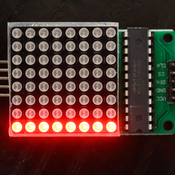
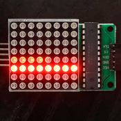
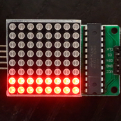
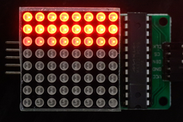
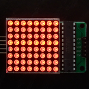
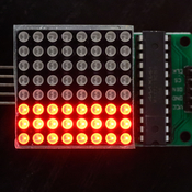
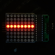
This device is a very simple moving LED bar, which can be set to strobe at standard camera shutter speeds 1/32, 1/64, 1/128, 1/256 & 1/1024s by pushing the button.
(Note these are the genuine speeds, not the humanised 1/30, 1/125, 1/250...) speeds

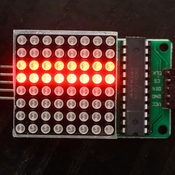
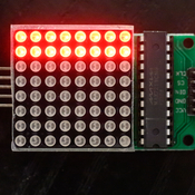
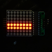
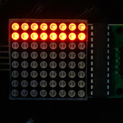
Each row of LEDs is illumintaed to the set time (1/32s) for example, then extingished as the next row lights.

Setting the LEDs to strobe at the same as the camera shutter speed will result in two (sometimes one) line of LEDs being photograped (using a digital camera). If 3 or more rows are photographed, then it is an indication that the shutter speed is slow. (Set tke LEDs to 1/512 but the camera to 1/30, to see this effect)

For a film camera, remove the lens, open the back of the camera. When the shutter is operated you will see through the camera to the LED matrix. You will see the ame LED pattern as decribed above.

Only four parts are required,
Arduino Nano (or Uno) board,
LED matrix
Push-button (This is not even needed, you could just touch two wires together)
Two Dupont wires (or any bit of wire if you want to solder directly to the Arduino board)

Parts & links to them, as well as build docs & firmware are all in the files.


randongsanzi

Member
Joined
Mar 16, 2024
Messages
5
Location
中国黑龙江省
Format
35mm
你好,我又遇到新问题了。Arduino捕获的blik.ino.hex文件如何使用?您想将文件名更改为Shutter_Tester_LED_0_0_1吗?我对这个程序实在是一无所知,所以希望你能帮我解决一下。谢谢你!
 
OP
OP

Niglyn

Member
Joined
Feb 26, 2022
Messages
408
Location
Surrey, UK
Format
Analog
你好,我又遇到新问题了。Arduino捕获的blik.ino.hex文件如何使用?您想将文件名更改为Shutter_Tester_LED_0_0_1吗?我对这个程序实在是一无所知,所以希望你能帮我解决一下。谢谢你!

Hi,
The firmware is supplied as a .hex file and must be flashed to the Arduino.
The file name should not be changed.

The program required to flash the firmware this is called AVRDUDESS

This program (and drivers if required) are in the Github repository.

The instructions, how to use AVRDUDESS are in the Github titled
'Optical Shutter Tester Firmware Load'

I have just numbered the documents on Github, to make them easier to follow
and put the firmware in a folder called 'Firmware'


Please keep us update on your progress :surprised:)


alinCiortea

Member
Joined
Jan 1, 2008
Messages
74
Location
Romania
Format
Multi Format
Hey, Niglyn!

I'm in the process of building the optical tester and I've already run into problems trying to flash the firmware.
I get this error (tried both Uno and Nano presets):

>>>: avrdude -c arduino -p m328p -P COM6 -b 115200 -U flash:w:"D:\tinkering\arduino\optical shutter tester\Shutter_Tester_LED_0_0_1.ino.hex":a
avrdude.exe: stk500_recv(): programmer is not responding
avrdude.exe: stk500_getsync() attempt 1 of 10: not in sync: resp=0xc8
avrdude.exe: stk500_recv(): programmer is not responding
avrdude.exe: stk500_getsync() attempt 2 of 10: not in sync: resp=0xc8
avrdude.exe: stk500_recv(): programmer is not responding
avrdude.exe: stk500_getsync() attempt 3 of 10: not in sync: resp=0xc8
avrdude.exe: stk500_recv(): programmer is not responding
avrdude.exe: stk500_getsync() attempt 4 of 10: not in sync: resp=0xc8
avrdude.exe: stk500_recv(): programmer is not responding
avrdude.exe: stk500_getsync() attempt 5 of 10: not in sync: resp=0xc8
avrdude.exe: stk500_recv(): programmer is not responding
avrdude.exe: stk500_getsync() attempt 6 of 10: not in sync: resp=0xc8
avrdude.exe: stk500_recv(): programmer is not responding
avrdude.exe: stk500_getsync() attempt 7 of 10: not in sync: resp=0xc8
avrdude.exe: stk500_recv(): programmer is not responding
avrdude.exe: stk500_getsync() attempt 8 of 10: not in sync: resp=0xc8
avrdude.exe: stk500_recv(): programmer is not responding
avrdude.exe: stk500_getsync() attempt 9 of 10: not in sync: resp=0xc8
avrdude.exe: stk500_recv(): programmer is not responding
avrdude.exe: stk500_getsync() attempt 10 of 10: not in sync: resp=0xc8
avrdude.exe: opening programmer "arduino" on port "COM6" failed

avrdude.exe done. Thank you.


The Arduino is a chinese clone from alixpress (the one in your link). Is it possible that it's defective?
I did the mistake of only buying one. I still have another Nano clone that I've been using for the 2 sensor tester but that one has the soldered pins and I've already cut a hole for the USB connection in my project box in a position that won't allow for the soldered pins.
Should I try to reflash the bootloader or is there some other way to test if the board is ok?

Thanks!
 
Last edited:
OP
OP

Niglyn

Member
Joined
Feb 26, 2022
Messages
408
Location
Surrey, UK
Format
Analog
Hey, Niglyn!

I'm in the process of building the optical tester and I've already run into problems trying to flash the firmware.
I get this error (tried both Uno and Nano presets):

>>>: avrdude -c arduino -p m328p -P COM6 -b 115200 -U flash:w:"D:\tinkering\arduino\optical shutter tester\Shutter_Tester_LED_0_0_1.ino.hex":a
avrdude.exe: stk500_recv(): programmer is not responding
avrdude.exe: stk500_getsync() attempt 1 of 10: not in sync: resp=0xc8
avrdude.exe: stk500_recv(): programmer is not responding
avrdude.exe: stk500_getsync() attempt 2 of 10: not in sync: resp=0xc8
avrdude.exe: stk500_recv(): programmer is not responding
avrdude.exe: stk500_getsync() attempt 3 of 10: not in sync: resp=0xc8
avrdude.exe: stk500_recv(): programmer is not responding
avrdude.exe: stk500_getsync() attempt 4 of 10: not in sync: resp=0xc8
avrdude.exe: stk500_recv(): programmer is not responding
avrdude.exe: stk500_getsync() attempt 5 of 10: not in sync: resp=0xc8
avrdude.exe: stk500_recv(): programmer is not responding
avrdude.exe: stk500_getsync() attempt 6 of 10: not in sync: resp=0xc8
avrdude.exe: stk500_recv(): programmer is not responding
avrdude.exe: stk500_getsync() attempt 7 of 10: not in sync: resp=0xc8
avrdude.exe: stk500_recv(): programmer is not responding
avrdude.exe: stk500_getsync() attempt 8 of 10: not in sync: resp=0xc8
avrdude.exe: stk500_recv(): programmer is not responding
avrdude.exe: stk500_getsync() attempt 9 of 10: not in sync: resp=0xc8
avrdude.exe: stk500_recv(): programmer is not responding
avrdude.exe: stk500_getsync() attempt 10 of 10: not in sync: resp=0xc8
avrdude.exe: opening programmer "arduino" on port "COM6" failed

avrdude.exe done. Thank you.


The Arduino is a chinese clone from alixpress (the one in your link). Is it possible that it's defective?
I did the mistake of only buying one. I still have another Nano clone that I've been using for the 2 sensor tester but that one has the soldered pins and I've already cut a hole for the USB connection in my project box in a position that won't allow for the soldered pins.
Should I try to reflash the bootloader or is there some other way to test if the board is ok?

Thanks!

Hi, if you are familiar with Arduinio, you could try using Arduino IDE and loading the Blink sketch.

Remember, most Chinese clones require 'Use Old Bootloader to be selected in the IDE.
Also, the Arduino boards (and clones) normally come with Blink sketch pre-loaded, so just plugging the Nano into the USB should make the LED blink.

Does your computer make a sound when connecting or disconnecting USB devices? If so does your computer make this sound when connecting the Nano?

Open Device Manager on your computer. In the Ports tab, you should see a 'CH340' device connected when the Nano is connected. Unplug the Nano and CH340 should disappear.
 

alinCiortea

Member
Joined
Jan 1, 2008
Messages
74
Location
Romania
Format
Multi Format
Alright... I just installed the latest version of Arduino IDE, uploaded the blinker sketch and one red led flashes on the board, so it seems it's somewhat functional. What should I do next? (I'll try the firmware flash again until you have the chance to reply)

LE: same error unfortunately...
 
OP
OP

Niglyn

Member
Joined
Feb 26, 2022
Messages
408
Location
Surrey, UK
Format
Analog
Hey, Niglyn!

I'm in the process of building the optical tester and I've already run into problems trying to flash the firmware.
I get this error (tried both Uno and Nano presets):

>>>: avrdude -c arduino -p m328p -P COM6 -b 115200 -U flash:w:"D:\tinkering\arduino\optical shutter tester\Shutter_Tester_LED_0_0_1.ino.hex":a
avrdude.exe: stk500_recv(): programmer is not responding
avrdude.exe: stk500_getsync() attempt 1 of 10: not in sync: resp=0xc8
avrdude.exe: stk500_recv(): programmer is not responding
avrdude.exe: stk500_getsync() attempt 2 of 10: not in sync: resp=0xc8
avrdude.exe: stk500_recv(): programmer is not responding
avrdude.exe: stk500_getsync() attempt 3 of 10: not in sync: resp=0xc8
avrdude.exe: stk500_recv(): programmer is not responding
avrdude.exe: stk500_getsync() attempt 4 of 10: not in sync: resp=0xc8
avrdude.exe: stk500_recv(): programmer is not responding
avrdude.exe: stk500_getsync() attempt 5 of 10: not in sync: resp=0xc8
avrdude.exe: stk500_recv(): programmer is not responding
avrdude.exe: stk500_getsync() attempt 6 of 10: not in sync: resp=0xc8
avrdude.exe: stk500_recv(): programmer is not responding
avrdude.exe: stk500_getsync() attempt 7 of 10: not in sync: resp=0xc8
avrdude.exe: stk500_recv(): programmer is not responding
avrdude.exe: stk500_getsync() attempt 8 of 10: not in sync: resp=0xc8
avrdude.exe: stk500_recv(): programmer is not responding
avrdude.exe: stk500_getsync() attempt 9 of 10: not in sync: resp=0xc8
avrdude.exe: stk500_recv(): programmer is not responding
avrdude.exe: stk500_getsync() attempt 10 of 10: not in sync: resp=0xc8
avrdude.exe: opening programmer "arduino" on port "COM6" failed

avrdude.exe done. Thank you.


The Arduino is a chinese clone from alixpress (the one in your link). Is it possible that it's defective?
I did the mistake of only buying one. I still have another Nano clone that I've been using for the 2 sensor tester but that one has the soldered pins and I've already cut a hole for the USB connection in my project box in a position that won't allow for the soldered pins.
Should I try to reflash the bootloader or is there some other way to test if the board is ok?

Thanks!


Hi, looking at your fault log, looks like you have the wrong baud rate set. Should be 57600.
I have downloaded the file from Github & flashed it to a nano clone, to test & it worked fine at 56700, but did not load at 115200

Capture.JPG
 

alinCiortea

Member
Joined
Jan 1, 2008
Messages
74
Location
Romania
Format
Multi Format
yes! it worked!
so basically you need 57600 baud rate for the old bootloader and 115200 for the new one, right? (it wasn't explicit in the firmware pdf on github and I was under the impression that 115200 is the correct one regardless of board)
Although it didn't work with Arduino Nano preset selected. I used Uno with 57600 baud and that fixed it.
 
OP
OP

Niglyn

Member
Joined
Feb 26, 2022
Messages
408
Location
Surrey, UK
Format
Analog
yes! it worked!
so basically you need 57600 baud rate for the old bootloader and 115200 for the new one, right? (it wasn't explicit in the firmware pdf on github and I was under the impression that 115200 is the correct one regardless of board)
Although it didn't work with Arduino Nano preset selected. I used Uno with 57600 baud and that fixed it.

Hi, Glad you have the firmware loaded ok

Just checked firmware load documents for both shutter tester and optical shutter tester. They both clearly highlight the two options of baud rate and the optical tester has big red arrows,

I appreciate flashing firmware can be very complex and confusing. If you have any ide of how to make any of my documents clearer, or find errors, please let me know & I will update them.

Let me know how you get on with the optical tester :surprised:)

Capture.JPG
 

alinCiortea

Member
Joined
Jan 1, 2008
Messages
74
Location
Romania
Format
Multi Format
Yeah, in the document there's one printscreen with the baud rate at 57600 and the preset on Arduino Nano (the one with the red arrows), and another slide with the baud rate at 115200 and the preset on Arduino Uno. In my case the winning combination was baud rate at 57600 and the preset on Arduino Uno.

I'll show you the end result soon, but in the mean time I have some preliminary conclusions... while testing a FED2, the most visible and obvious results are for 1/500, followed by 1/250. The only time I managed to get more than 3 lines was when using the tester at 1024 and the shutter at 1/500. If using a slower shutter I only get a 'handful' of lit LEDs. Do you know what accuracy I can expect? (I'll try to play with a one stop difference and see if I get consistent results.)

As for suggestions, I'd suggest making the shutter start at a different speed (my preference would be 512), or maybe at the last used speed if that's possible. Also, if possible, make the button quickly cycle through the settings instead of having to wait until the LEDs show the selected speed entirely.
 
OP
OP

Niglyn

Member
Joined
Feb 26, 2022
Messages
408
Location
Surrey, UK
Format
Analog
HI,
Latest version of code has been uploaded to Github.

Following on from alinCiortea's feedback, the following is changed-

Pressing the button during the flash screen will skip it & go straight to testing.

Pressing the button will now quickly cycle through all of the speeds, you do not have to wait for the selected speed to be shown in it's entirety.

Thanks for the feedback. All feedback, comments and suggestions are most welcome. This way I can improve my photographic projects.
 
Last edited:
OP
OP

Niglyn

Member
Joined
Feb 26, 2022
Messages
408
Location
Surrey, UK
Format
Analog
Now the question about accuracy. The answer is very accurate. The controller runs at nS speeds and we are testing to only mS speeds.

The issue arises as there is no synchronisation between the tester and the camera, so you may get a reading just as the tester changes the LED row or conversely, just when it is about to change the row.

An example at 1/60s
Row 1 is turned on, row 8 is turned off then wait for 1/60s
Row 2 is turned on row 1 is turned off then wait for 1/60s
Row 3 is turned on, row 2 is turned off then wait for 1/60s
Row 4 is turned on, row 3 is turned off then wait for 1/60s
Row 5 is turned on, row 4 is turned off then wait for 1/60s
Row 6 is turned on, row 5 is turned off then wait for 1/60s
Row 6 is turned on, row 6 is turned off then wait for 1/60s
Row 7 is turned on, row 7 is turned off then wait for 1/60s

So, a camera at 1/60s will show 1 or2 rows.
Photos show LED matrix set at 1/60s with camera set at 1/60s
 

Attachments

  • 1_60_strobe_1_60_camera.jpg
    1_60_strobe_1_60_camera.jpg
    835.7 KB · Views: 12
  • 1_60_strobe_1_60_camera-2.jpg
    1_60_strobe_1_60_camera-2.jpg
    964.6 KB · Views: 16
  • 1_60_strobe_1_60_camera-3.jpg
    1_60_strobe_1_60_camera-3.jpg
    923.8 KB · Views: 10
  • 1_60_strobe_1_60_camera-4.jpg
    1_60_strobe_1_60_camera-4.jpg
    844.4 KB · Views: 12
  • 1_60_strobe_1_60_camera-5.jpg
    1_60_strobe_1_60_camera-5.jpg
    899 KB · Views: 13
OP
OP

Niglyn

Member
Joined
Feb 26, 2022
Messages
408
Location
Surrey, UK
Format
Analog
These photos show the camera set at 1/60s, but with the LED matrix set at 1/125, 1/250, 1/1000s
So we can see there are more LED rows lit, indicating the shutter is running slow (we know it is as it is set to 1/60s.
 

Attachments

  • 1_60_strobe_1_60_camera-5.jpg
    1_60_strobe_1_60_camera-5.jpg
    899 KB · Views: 13
  • 1_125_strobe_1_60_camera.jpg
    1_125_strobe_1_60_camera.jpg
    806.8 KB · Views: 12
  • 1_1000_strobe_1_60_camera.jpg
    1_1000_strobe_1_60_camera.jpg
    952.6 KB · Views: 12
  • 1_250_strobe_1_60_camera.jpg
    1_250_strobe_1_60_camera.jpg
    729 KB · Views: 14
OP
OP

Niglyn

Member
Joined
Feb 26, 2022
Messages
408
Location
Surrey, UK
Format
Analog
Setting the camera to 1/250s.
Majority photos with LED matrix running at 1/30s, 1/60s or 1/125s show just one LED row. (shutter running fast). There will be a few photos with two rows (as shown below) but these should be the minority.

With the LED matrix at 1/250s, we are back to most photos showing two lines of LEDS
and moving the LEDs to run at 1/500s, we are back to seeing three rows of LEDs as the camera shutter is at 1/250s, thus running slow.

The optical tester will only give an estimate and is best showing that a shutter is running slow.

A good way to test is to set the camera to 1/125s. Start the LED matrix at 1/30s and take some photos whilst looking through the film gate. Increase the LED matrix speed one stop at a time & repeat. When it is found that constantly only two rows of LEDs can be seen, this will be an indication of the camera's shutter speed.

The optical tester will only give an estimate and is best showing that a shutter is running slow.
 

Attachments

  • 1_125_strobe_1_250_camera_2.jpg
    1_125_strobe_1_250_camera_2.jpg
    843.5 KB · Views: 12
  • 1_125_strobe_1_250_camera.jpg
    1_125_strobe_1_250_camera.jpg
    830.6 KB · Views: 10
  • 1_250_strobe_1_250_camera_2.jpg
    1_250_strobe_1_250_camera_2.jpg
    665.2 KB · Views: 13

alinCiortea

Member
Joined
Jan 1, 2008
Messages
74
Location
Romania
Format
Multi Format
That's awesome!
I've flashed the new firmware and it's exactly what I suggested, except that 1/1000 is missing now :D
I'd say though that the initial speeds shown were a bit better (but in the rounded form - 30 / 60 / 125 and so on), meaning without "1/" in front of them. It's easier to quickly spot what you've selected.

Thanks so much for your patience, promptness and in-depth answers. I've made a video about building the box that I've uploaded on youtube before your firmware update and while recording the video I actually understood (I think) how to read the tester. It's certainly a part of my 'box of tools' now.
And I'll start working on the bigger tester (the version with a film gate sensor module and external light source) the following days.

If anyone's curious, this is the video

I've rewatched it and I'm aware I've said some bits of stupidity but, again, I kind of made sense of how it works while I was filming the video :D

I've posted in the description all the links to github, photrio, credits and so on.
 
OP
OP

Niglyn

Member
Joined
Feb 26, 2022
Messages
408
Location
Surrey, UK
Format
Analog
Hi, great video. Shame it is not of the newer firmware, I had not spotted the old version 0_1 was on github, which showed the incorrect shutter speed display.

This has now been corrected to show the humanised 1/125, 1/250, 1/500, 1/1000
but inside it uses the actual speeds of 1/30, 1/60, 1/120, 1/240, 1/480, 1/960

Further tweaks allow skipping of the start-up screen showing firmware version by pressing the button.
I like the FW version to be displayed, as it helps with feedback & grumbles if I know which version is running.

I could not get 1/1000s to work reliably, which is why I removed it in 0_4 but moments later I found inspiration & it is back in _0_5.
It was simply caused by the LEDs light decay rate, so the previous row was still emitting a bit of light. Turning the LED brightness down solved the issue :surprised:)

The code is really simple. It just bit-bangs the whole row off (send a byte of 0s) ands the same to turn the next row on (send one byte all 1s) in a loop corresponding to the set shutter speed.

I have taken some better photographs showing the results and these are now included in the user guide. These are taken with a digital camera, so show ideal images, you will obviously not see such clarity when peering through the film gate.

I'm always grateful for feedback & suggestions for improvements for my projects & also welcome ideas for new ones.

Tester running at 1/250s and the camera shutter correctly running at 1/250s

1_250_Both (1).jpg


Tester running at 1/250s but the camera shutter speed is slow & running at 1/60s, The extra 2 stops can be seen.
1_250_strobe_1_60_camera.jpg
 

alinCiortea

Member
Joined
Jan 1, 2008
Messages
74
Location
Romania
Format
Multi Format
Very nice!
Yeah, as soon as I posted the video I saw your update :D

Using a conventional cloth shutter looks indeed different and I think some exercise is needed to 'learn' how to read it. I'll have to build the 'true' shutter tester, find one camera that is as close as possible to having an accurate shutter and then use that camera to learn the optical shutter's reading.

For the higher shutter speeds I've found so far that it's about the number of light strips, not necessarily the number of light rows within each strip. And that makes sense, since a wider gap between the curtains will allow more leds from the same row to be visible, creating thinner or thicker strips.
But overall it's a super nice addition to the armamentarium, especially since it's so cheap and easy to build.

It would probably work even nicer with a denser LED array, if such an array would be available.
 

alinCiortea

Member
Joined
Jan 1, 2008
Messages
74
Location
Romania
Format
Multi Format
I've just uploaded ver. 0_5 but 1/1000 is still missing.
Another issue that I've seen is that many times pressing the button once skips a setting (jumps from 30 to 125 and so on). Most likely it's a faulty button, right?
Also, any chance you could also upload a firmware version that ditches the "1/" in front of the setting? For me personally it would work much better if the settings simply displayed the setting (for when I need to quickly cycle to a different one).


LE: This is how it behaves. I've opened up the box and checked the button for continuity. It seems to be fine (shows continuity when pressed but never when it's not pressed or between actuations)

 
Last edited:
OP
OP

Niglyn

Member
Joined
Feb 26, 2022
Messages
408
Location
Surrey, UK
Format
Analog
I've just uploaded ver. 0_5 but 1/1000 is still missing.
Another issue that I've seen is that many times pressing the button once skips a setting (jumps from 30 to 125 and so on). Most likely it's a faulty button, right?
Also, any chance you could also upload a firmware version that ditches the "1/" in front of the setting? For me personally it would work much better if the settings simply displayed the setting (for when I need to quickly cycle to a different one).


LE: This is how it behaves. I've opened up the box and checked the button for continuity. It seems to be fine (shows continuity when pressed but never when it's not pressed or between actuations)


Hi,

I have added more time to allow for button bounces and removed the "1/" in version 0_0_6 of the firmware.

You are experiencing 'bounce' which is caused by a switch making & breaking contact thousands of time a second whist being pressed or released, before finally deciding to be made or broken.

All mechanical switches do this. This is fine for light switches, but for micro-controllers it is very problematic as the micro-controller is reading the switch thousands of times a second, so it 'sees' multiple presses & thinks the user is pressing the button.

The time & number of bounces will vary depending on the quality of the switch. Most of my projects use clever code which detects rapid button pushes (i.e bounces) and ignores them. However, for this optical tester, the code is minimal and uses a simple delay after each button-push, to give time for the bounces.

Let me know if this code works ok for you.
 
OP
OP

Niglyn

Member
Joined
Feb 26, 2022
Messages
408
Location
Surrey, UK
Format
Analog
Fabulous! It's spot on!
Much appreciated, thank you! :smile:

I made the device as a quick simple demo, but like most of my projects they evolve & grow.

The next version is already sitting here, it now uses better timing which takes into account the code execution time.
Not really needed as we are working with old cloth shutters, but I like things to be accurate & correct :surprised:)
 
Photrio.com contains affiliate links to products. We may receive a commission for purchases made through these links.
To read our full affiliate disclosure statement please click Here.

PHOTRIO PARTNERS EQUALLY FUNDING OUR COMMUNITY:


Ilford ADOX Freestyle Photographic Stearman Press Weldon Color Lab Blue Moon Camera & Machine
Top Bottom