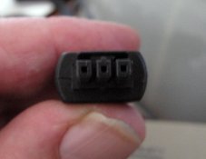
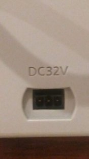
Well, *that* doesn't make much sense...seems like Mr. Murphy has stepped in to make life interesting.
Thank you,
tokam, for making those measurements!
Someone in the Flickr conversation says he took the scanner apart and claims the center pin is GND.
But I'm at a loss to figure out how that matches up with the voltages you measured.
A possible next step would be to take the scanner apart and try to understand the circuitry connected
to the pins, and figure out what voltages it wants to see. That's possible, and I have done it, but it
takes a lot of experience and not a small bit of luck.
Another possibility is to measure the voltages with the scanner connected and powered on.
Often, these switching supplies do not regulate their outputs well until a load is connected.
Again, this is a probably an exercise for "advanced students".
I believe this scanner has an LED light source. These are sometimes powered by current-regulated
supplies, and this could be the purpose of the third pin. If this is the case, you would not see a
stable voltage on that pin, it would be whatever voltage is necessary to get the specified current
to flow through the LEDs. We just don't know if this is the case.
It may be that this is beyond us. It's probably a good thing that Craig has purchased another scanner

I'm sorry I couldn't have been more help. I can promise you that if I ever run across one of these scanners,
I will have an irresistable desire to disassemble it, and post my findings on the web somewhere!


 :
:


