albada
Subscriber
Here's an accurate reflection densitometer that costs $120, which is far less than anything else on the market. It consists of an enlarger meter from Darkroom Automation, and a home-made attachment containing an LED.

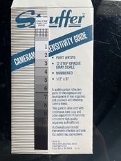
It's accurate! Measurements from this simple attachment differ from my calibrated Stouffer reflection step-tablet by at most 0.02. First, here's the enlarger meter by itself. This picture was taken from http://www.darkroomautomation.com/em.htm .

I taped a white piece of paper to the top of my meter to give me a larger view of the surroundings, making it easier to find a spot I want to meter on the easel. This addition is unrelated to the densitometer.
You will need a high-power LED, which you can take out of an LED torch (flashlight). This is a good use of a torch that was ruined by leaking batteries. Below, you see that I desoldered and removed one LED.

The torch had a clear plastic cover, shown on the right side of the photo above. Keep it. You will use it to hold the print flat on top of the densitometer. The light spot from the LED is so bright that the image shows through the back of the print, so using this clear cover allows you to see exactly what spot on the print you are measuring.
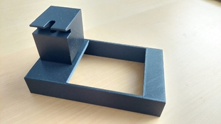
The sheet metal merely holds the wood block in the correct position. You can use pieces of wood instead if you don't have access to sheet metal. In fact, I recommend building a rectangle that barely touches the meter on all four sides, as that will hold the LED-block in place in all directions. My poorer design allows the attachment to slip northward of the meter.
The wood block has a corner-to-top 45-degree hole through which the LED shines up to the top, and a vertical hole over the meter's sensor. The photo below looks directly down the 45-degree hole. I suggest making the vertical hole 6mm in diameter (1/4 inch), and the 45-degree hole just large enough to allow the upper portion of the LED to slide into it. The bottom of the LED has a flared lip that can remain outside the hole. The reason for making this hole as small as possible is to minimize the spot-size at the top, thus minimizing the diameter of the troublesome specular reflection described below.

The diagram below shows a side-view of the light-path through the wood block.

The LED at the lower left shines its beam up the 45-degree hole, which reflects off the print on the top. This reflection consists of a diffuse component which travels down the vertical hole and onto the sensor, and a 45-degree specular component which can only cause flare. I cut a notch in the side of the block to allow the specular beam to escape without causing flare. I painted the area around the top black to cut flare even more. Also, the first photo above shows a vertical notch cut in the top to allow the specular reflection to escape without touching any wood, causing flare. That's the key: remove all wood from the path of that specular reflection.
Flare is the enemy when measuring dark areas, because a little flare will cause near-blacks to appear significantly lighter. Those two notches conquered flare: My measurement of the darkest patch on the calibrated Stouffer tablet was 0.01 higher (darker) than Stouffer's measurement. Flare would have made my density measurement lower, not higher.
To operate the LED, find a 5-volt switching power-supply, such as those for consumer electronics or USB. Obtain several 100-ohm resistors rated for 1/2 watt or higher. These can be purchased cheaply from electronics suppliers such as digikey.com, mouser.com, and newark.com. I found that 300 ohms (three resistors) in series with the LED is perfect: the spot's brightness reflecting off white paper is near the meter's upper limit. You might find that 200 or 400 ohms is best with your LED.
I should mention that the meter measures in stops, which you must multiply by 0.301 to get log D. Instead of doing that, I convert my desired densities to stops by dividing them by 0.301.
The densitometer is stable. When measuring densities, I always zero the meter on white paper, putting the meter in "delta mode". After 10-15 minutes of measuring many test-patches for H-D curves, I always re-check the zeroing by measuring white again. It always remains at 0.00. That's stability. And a max 0.02 error is good accuracy.
Mark Overton
It's accurate! Measurements from this simple attachment differ from my calibrated Stouffer reflection step-tablet by at most 0.02. First, here's the enlarger meter by itself. This picture was taken from http://www.darkroomautomation.com/em.htm .
I taped a white piece of paper to the top of my meter to give me a larger view of the surroundings, making it easier to find a spot I want to meter on the easel. This addition is unrelated to the densitometer.
You will need a high-power LED, which you can take out of an LED torch (flashlight). This is a good use of a torch that was ruined by leaking batteries. Below, you see that I desoldered and removed one LED.
The torch had a clear plastic cover, shown on the right side of the photo above. Keep it. You will use it to hold the print flat on top of the densitometer. The light spot from the LED is so bright that the image shows through the back of the print, so using this clear cover allows you to see exactly what spot on the print you are measuring.
The sheet metal merely holds the wood block in the correct position. You can use pieces of wood instead if you don't have access to sheet metal. In fact, I recommend building a rectangle that barely touches the meter on all four sides, as that will hold the LED-block in place in all directions. My poorer design allows the attachment to slip northward of the meter.
The wood block has a corner-to-top 45-degree hole through which the LED shines up to the top, and a vertical hole over the meter's sensor. The photo below looks directly down the 45-degree hole. I suggest making the vertical hole 6mm in diameter (1/4 inch), and the 45-degree hole just large enough to allow the upper portion of the LED to slide into it. The bottom of the LED has a flared lip that can remain outside the hole. The reason for making this hole as small as possible is to minimize the spot-size at the top, thus minimizing the diameter of the troublesome specular reflection described below.
The diagram below shows a side-view of the light-path through the wood block.
The LED at the lower left shines its beam up the 45-degree hole, which reflects off the print on the top. This reflection consists of a diffuse component which travels down the vertical hole and onto the sensor, and a 45-degree specular component which can only cause flare. I cut a notch in the side of the block to allow the specular beam to escape without causing flare. I painted the area around the top black to cut flare even more. Also, the first photo above shows a vertical notch cut in the top to allow the specular reflection to escape without touching any wood, causing flare. That's the key: remove all wood from the path of that specular reflection.
Flare is the enemy when measuring dark areas, because a little flare will cause near-blacks to appear significantly lighter. Those two notches conquered flare: My measurement of the darkest patch on the calibrated Stouffer tablet was 0.01 higher (darker) than Stouffer's measurement. Flare would have made my density measurement lower, not higher.
To operate the LED, find a 5-volt switching power-supply, such as those for consumer electronics or USB. Obtain several 100-ohm resistors rated for 1/2 watt or higher. These can be purchased cheaply from electronics suppliers such as digikey.com, mouser.com, and newark.com. I found that 300 ohms (three resistors) in series with the LED is perfect: the spot's brightness reflecting off white paper is near the meter's upper limit. You might find that 200 or 400 ohms is best with your LED.
I should mention that the meter measures in stops, which you must multiply by 0.301 to get log D. Instead of doing that, I convert my desired densities to stops by dividing them by 0.301.
The densitometer is stable. When measuring densities, I always zero the meter on white paper, putting the meter in "delta mode". After 10-15 minutes of measuring many test-patches for H-D curves, I always re-check the zeroing by measuring white again. It always remains at 0.00. That's stability. And a max 0.02 error is good accuracy.
Mark Overton


