• Welcome to Photrio!
    Registration is fast and free. Join today to unlock search, see fewer ads, and access all forum features.
    Click here to sign up

Yashica Mat 124 full fledge CLA

Forum statistics

Threads
204,390
Messages
2,867,849
Members
102,247
Latest member
callmedos
Recent bookmarks
0

Laurent

Subscriber
Joined
Oct 15, 2004
Messages
1,900
Location
France
Format
Multi Format
The Yashica Mat 124 (I’ll write « Mat » for now to save space) was my first TLR (long story short : I won the bid on eB*y because I was frustrated I could not get hold of any Zorki … ) and I loved it as it opened new ways of seeing the world.


When it began acting, I sent it for a CLA which was fine until a few months later the shutter started getting sticky again. I fixed the issue by myself but did no longer trust the camera, so I traded a Sinar F for a Rolleiflex 3.5. Then I felt the Mat was one camera to much so I sold it.


I came to cameras maintenance for fun (see the other thread) and recently found a cheap enough Mat, the same I had some years ago. So I pulled the trigger and soon enough I’ve got a new (to me) Mat in need of a thorough CLA.


What I could see immediately :

  • missing screws (on the hood but not only)
  • meter « window » not in proper place
  • meter not working (see above…)
  • speed and aperture « window » missing
  • sticky shutter that would sometimes operate fine, but even in these cases winding it was necessary to have the leaves close fully.
  • Missing leatherette except on the back.
  • Focus was a bit stiff.
  • Somebody tried to do a paint job, I don’t know if they wanted it to look like a 124 « G » but they applied black paint in many places. I have no images of the initial status of the camera but this one gives you an idea...

IMG_5534_small.JPG


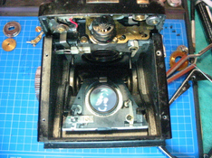
When I open the camera, I could see LOTS of grease, which seem way too much for me (I like mechanism lubricated just enough) so I plan to do a clean up, which may cure the stiff focusing in the mean time.

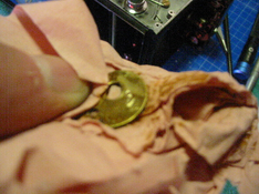
On the image below, notice I’ve already replaced the broken wire for the meter, which did not solve the issue (but the « window » is still in a wrong place).


IMG_5272_small.JPG


The first thing I did was to remove the meter assembly, and get the window back in place, held with some Pliobond (I hate this glue, as it smells awful, but it does the job) and… TADAAAA !!!* the meter works !

* ( I know, several exclamation marks are the indication of a deranged mind, according to St Terry, but well, I never pretended to be sane ! )

This is really encouraging as it shows the camera’s issues may be solved at home...

To help me in the CLA, which will be a first one as I plan on fixing the shutter myself, I looked for information sources :

- Benoit Suaudeau has a tutorial about opening Yashica TLRs : Yashica mat disassembly

- LearnCameraRepair.com has a nice tutorial about CLAing the same cameras : Yashica mat CLA tutorial by E.Pate It covers the shutter disassembly

- Spoiler alert : the same site has a Copal SVE guide, which does not really apply to the Copal SV (don’t ask me how I know) so you can spare the expense.

- YashicaTLR.com is a good source for information : yashicatlr.com

- The general diagrams for the camera are available in many places (but I can’t find a link at the moment, I’m working from a download…)


Note : anything beyond this point may damage the camera, so you are on your own…

Be careful with the solvents you use, make sure you’re working in a well ventilated room.

Removing the cover plate is easy, especially since there was no leatherette… Five screws and you’re done.

IMG_5397_small.JPG


Next step is removing the lenses plate, which leaves you with an almost empty shell and the lenses and shutter on their plate.

IMG_5398_small.JPG


Not show here : under the lens plate are some washers which manage the parallelism between the lens plate and the film plane… Make sure you do not lose them and you know where they go. The best way I found is that I put them back in place and screwed the screws back in place to hold them.

On the back of the plate, remove the ring that secures the shutter assembly and is used as a light baffle at the same time.


IMG_5399_small.JPG


The ring you see there is part of the winding mechanism and is also used in the management of the triggering/winding process. Remove the tiny spring before you remove the ring.


IMG_5401_small.JPG


Or course, you will also remove the two parts of the lens. A spanner is indicated, my Mat shows sign of careless disassembly in this area.


IMG_5402_small.JPG


IMG_5403_small.JPG


Next step is to remove the sync wire. My soldering iron is ugly and a bit big, but it does a good job as it’s powerful enough to unsolder in a second, which causes less damage than a weak iron that takes ages.

IMG_5404_small.JPG


Note the viewing lens is still in place. I did not remove it so that I did not have to synchronize it again with the taking lens. YMMV…


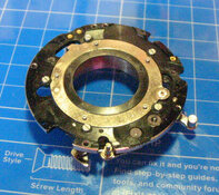
When the shutter is free, it’s time to remove everything until you can access the leaves for it and the aperture. This step is a bit scary, as one always wonders if they will be able to put everything back in place…

Important notice : take many pictures, and write down every f***ing step and every bloody detail you can imagine. You WILL miss some information at one moment, the goal is to miss as few as possible…

I followed the tutorial for this, so I won’t show everything. The reassembly will be covered with more details (but you still need to write everything down!)

At one moment, your work mat will look something like this :


IMG_ShutterOnMap.jpg


My mat is the "iFixit" one, as are many of my tools. It's magnetic, which can be a blessing to avoid loosing parts, but may tiny parts of the Yashica are not magnetic (screws especially) so it will not be a 100% guarantee. Sometimes, magnetism will be a curse, for example when you move the shutter assembly a little and leaves fall apart again... Don't ask me how I know.

I think that's it for this post, stay tuned for the next
 
An excellent report—very clear and a real page-turner.

Thank you very much! 😃

I see you're using the iFixit magnetic board for labeling? What's your experience with it?
 
An excellent report—very clear and a real page-turner.

Thank you very much! 😃

I see you're using the iFixit magnetic board for labeling? What's your experience with it?

Thanks, Andreas!
 
The shutter assembly is very modular, so it’s quite easy to remove almost everything.

The slow speeds governor is held by two screws, the self-timer by a E-ring (don’t let it fly away ! It’s very tiny)

IMG_5436_small.JPG


IMG_5438_small.JPG


IMG_5442_small.JPG

I chose not to remove the shutter mechanism itself, as it did not seem necessary and is made of many individual parts. I’m not sure this was the best option, as there were some contorsions to remove the two mechanisms, but it was doable.


I removed the shutter trigger lever, it’s held by only a pivot screw (this is the large brass screw visible here). Freeing the shutter from its’ housing is done by removing 4 screws that appear when the aperture lever is in the right position (see the 4 holes in the back plate)

IMG_5444_small.JPG


Surprise… when one removes the shutter from its’ housing, the leaves fall ! So now you know you HAVE to be able to put them back in place. It may be possible to separate the parts without letting the leaves get loose, but it’ll be tricky as the fit is very tight between the shutter and its’ home.

IMG_5448_small.JPG


1780430924017.jpeg


There will be smaller parts with the leaves, their rôle is not clear to me and I’ve read their place is critical. However, I was able to put the shutter together without knowing exactly how they were installed initially, with apparently zero issue… More on this later.


The aperture mechanism is below the shutter mechanism, in the same carter.

IMG_5452_small.JPG


When you open it the leaves get loose and you will be able to clean them.

IMG_5453_small.JPG


The blades are controlled by two discs that are connected to this bottom ring.

IMG_5454_small.JPG
IMG_5456_small.JPG


Notice the position of the two rings, there are many (wrong) ways of putting the back…

The rings are connected to the control ring by two tiny screws, and reassembling them can be tricky. I used « reverse tweezers » to keep everyting in place. (Yes it’s a very good idea to wear gloves, even when it’s hot ! It keeps your fingers « grippy » and saves the mechanism from getting some grease from your skin. The pictures when I do not wear them are usually from a dismounting phase)

IMG_5463_small.JPG
IMG_5464_small.JPG


This is not explicitly said in the tutorial, but the images show it clearly : putting the leaves back is much easier in the « wide open » position. In this position they are fully supported and will not fall.

IMG_5468_small.JPG


Note the blue marks in the housing, they were used to remember the relative positions of the parts. The lines show the place for the axles, the « strange » shape at the top corresponds to an opening in the plate that covers the aperture mechanism.

... 15 images limit reached, so I'll continue in the next post.
 

Attachments

  • IMG_5448_small.JPG
    IMG_5448_small.JPG
    144.4 KB · Views: 15
  • IMG_5448_small.JPG
    IMG_5448_small.JPG
    144.4 KB · Views: 16
What is not shown here is that all parts were carefully cleaned, there was oil litteraly everywhere. I used IPA for this, and cleaning paper. I lubricated the pivots again with Nyoil (I used an oil-pick for this, what you want is the tiniest amount), and the leaves themselves with graphite.

When you are done properly, the blades should open and close smoothly. When fully open, they should disappear behind the plates.

IMG_5469_small.JPG


Final comments for today:
- not shown here is that it took me several attempts to get the aperture back to a working status. Next time I'll be more cautious in writing every-effing-thing down.
- the tutorial says the remounting of these leaves and the shutter ones could be hours of fun...
- I can confirm, as this (including the shutter leaves) took me the best part of a day (think 4/5 hours on the bench)

See you later for the shutter part!
 
Very well done! Your photos are clear and illustrate each step of the process well. What occurs to me is a point that Dan Daniel made in another thread: there are many points of similarity between different cameras; once you've disassembled one TLR you probably have a basic understanding of most of them.
 
Great stuff @Laurent , well done and thanks for sharing. A really valuable bookmark.Thanks!

OneEyedPainter
 
Thanks for you comments!

Point of interest: the camera I'm using for the images is a Canon Powershot A40 "with professional features" (Canon dixit) and 2MP... It no longer works from batteries (I guess a negative lead is the culprit) and the flash seems dead, but it still does the job and gives smaller images than my phone, on top of being easier to use!

@Tel : the issue there is that I'll be tempted to check if all TLRs are created equal, and will soon be looking for another project camera!
 
Now the REAL fun begins… let’s have a look at the shutter itself !

Of course, the leaves have been very carefully cleaned before attempting the reassembly.

We are starting with the empty shutter plate, and will have to put the leaves back in place.

IMG_5470_small.jpg


The general positioning is as shown below. The leaves have two holes of different sizes, so it’s quite obvious. Note the scribe lines (« I », « II » etc) on the plate, that help in identifying which blade goes where. You may notice similar markings on the work mat. Notice also that of of the spacers in is the wrong position (the one that sits alone on the « II » position)

IMG_5471_small.jpg


The smaller blades act as spacers (at least this is my guess…) and I found that in my version I had to alternate, putting one spacer below the leave in a given place, then above next leave, etc. I’m not sure if I had 4 or 5 spacers to begin with, as I may have lost one (but I’m not sure and have no way of checking)


IMG_5472_small.jpg


This is how it should look at the end.

IMG_5473_small.jpg


I applied some Nyoil on the pivots, again using an oil pick to put only piny drops in the right place.

I found necessary to remove the flash sync contacts to have more room to put the mechanism back in place, so I did it at this stage. Note : I lost a small insulating part and am afraid Kapton tape does not do the job, so at the end I fear my sync plug is shorted. I did not try it yet.

IMG_5474_small.jpg


IMG_5476_small.jpg


I also removed the flash sync mechanism on the shutter main plate , as it was an additional protruding piece.

IMG_5477_small.jpg


Putting the shutter plate in the housing is a matter of patience and profanities… You have to blindly put the plate in the housing without seeing it (it has to remain in the position where the blades are on the up side, otherwise you’re back to start again. Don’t ask me how many times it happened (the most stupid is when I wanted to see where I was stuck… You may want to tilt the housing a bit, as some of the remaining parts are obstacles to putting everything in place. I guess next time I’ll remove everything and will see if it’s easier.

When you are there, put the four screws holding the plate in the housing back in place (the four screws that appear when the aperture ring is in the right position) so that the shutter is secured.

NORMALLY at this stage, you should be able to arm and trigger the shutter, you will only have Bulb, but you’ll be able to check the shutter operates crisply both on opening and closing. This may be the right moment to apply some graphite on the blades, as a lubricant.

You deserve a break, the rest is a piece of cake !

To put the flash mechanism back in place, a rubber band is used to keep the winding lever out of the way.

IMG_5479_small.jpg


Next comes the self timer. It is held in place by the small E-Ring (I hope you did not lose it!) and « indexed » by a brass post.
IMG_5488_small.jpg

IMG_5490_small.jpg


Then comes the slow speeds mechanism, which is secured by two screws.

IMG_5495_small.jpg


After these two parts are back in place, you can have the control ring on top of them. It should get back easily, and gives you a way to test different speeds.

IMG_5497_small.jpg


If you are satisfied, you can then put the « nut » that secures it, and lock it in place by turning the « half screw » (not really a screw, but it has a slotted head). In my case it took a bit more than one turn to have it back in the same position. I’m not 100 % sure this is critical, but why take risks ?

IMG_5499_small.jpg


Finally for this side, you can put the cam that transmits the speed information to the display on top of the camera. Two screws and two washers do the trick.

IMG_5501_small.jpg


That's it for today, you deserve a real rest and some patting in the back! (in real time, this represents one afternoon of work)

One thing I forgot to mention: many of the screws are held in place by a touch of clear nails polish, so that vibrations do not break havoc in the mechanics.

As a general comment, I'll add that I'm amazed at the clear design of the shutter. The sub-assemblies make it easy-ish to work on it, and the precision is such that the speeds seem accurate after reassembly. At least the slow ones, which were tested using Audacity as the opening and closing sounds are very clear.

In the next post, we’ll put the shutter back on the camera front plate…
 
The first four blades need the spacer under them; the last blade has it above. Usually the first blade is put on the post nearest to the main lever. But that's not critical. And I'd say it's risky to put oil anywhere near the blades. It can migrate and cause the blades to stick together.
 
The first four blades need the spacer under them; the last blade has it above. Usually the first blade is put on the post nearest to the main lever. But that's not critical. And I'd say it's risky to put oil anywhere near the blades. It can migrate and cause the blades to stick together.

Thanks for the precision!
It took me some time to decide what to do before putting a tiny drop of oil on the pivots. In the end I decided to do it, as I can always come back later to remove it !
 
OK, so now that the shutter assembly is fine, we'll put it back on its' plate...

Note : I will be using the parts’ name from the Yashica repair document, in this case I’ll put them in italics and add an asterisk after the name like this : sample name*. It’s more precise than inventing names that may only speak to me.

I started by a cleanup, as, as I said before, there was oil literally everywhere ! When dismantling the camera I was too focus on getting to the main point to do this properly, but I think it would have been a good idea… Some Q-tips and IPA later, the plate is clean and ready to get the lens back.


IMG_5505_small.jpg


The shutter cocking plate* gets between the shutter and the plate, and has a « proper » position.

IMG_5506_small.jpg


When the shutter is back in place, the connecting plate* links the mechanism in the body to the cocking mechanism in the lens plate. It has a proper position so that its’ rotation is limited to two extremes, and has an appendage that has to be sitting between two « prongs » of the shutter release.
IMG_5507_small.jpg
IMG_5508_small.jpg


This plate is held in place by the taking lens barrel* which acts both as a retainer for the shutter and a pivot for the connecting plate*.

IMG_5514_small.jpg


Of course, it is a better idea to put the rear lens element first, after a proper cleanup as it will be much less accessible later. I use a micro-fiber cloth to finalize the cleanup.


IMG_5509_small.jpg


IMG_5511_small.jpg


Finally, the little spring is put in place to set the plate back to its’ resting position after winding.

The shutter should be properly oriented so that it is correctly coupled to the rest of the camera. This is ensured by careful positioning (a brass rod has to be seated in the corresponding hole to achieve this.)

The shutter assembly has two cams that act on levers to transmit the exposure information to the meter assembly, make sure they are working correctly when you change the speed or aperture.
IMG_5513_small.jpg
IMG_5514_small.jpg


Finally, comes the time to solder the sync wire back to the flash sync coupler. (This time the soldering iron is the thin one, much less poserwul but more precise)

IMG_5517_small.jpg


The front plate can be left aside for the moment, as it is time to have a look at the focusing mechanism. (I processed this as a background task as I disassembled the focusing cams and shaft during a break and had them soaked in white spirit for a while).

A few days soaking and a careful cleaning with absorbing paper turned an awfully dirty mess to shiny parts…
IMG_5428_small.jpg

IMG_5432_small.jpg


I also removed the focusing arms* for a proper cleanup, and took the opportunity to clean the main body*


IMG_5561_small.jpg


IMG_5563_small.jpg


Oopsie! 15 images already, continuing on the next post...
 

Attachments

  • 1780947310822.png
    1780947310822.png
    384.9 KB · Views: 1
The inside cover* is held by 4 screws, two with a countersunk slotted head and two with a flat Philips head. I marked their position by a line (for slotted) or a cross (for Philips) so that I put them in the proper position later (the countersunk ones ensure the proper alignment of the cover)

IMG_5562_small.jpg


While the body is « naked », it is the right moment to hunt for the remaining grease everywhere (I removed the mirror to avoid damaging it, and to be able to clean it before putting it back)

IMG_5567_small.jpg


While inspecting the body, I found that not only the hood was missing 3 out of 4 screws (!) but also one was broken in the body. I used a 1.2 mm bit to remove all I could, then a M1.6 (metric) tap to restore the tapping.

IMG_5568_small.jpg
IMG_5569_small.jpg


IMG_5570_small.jpg


I had a look for screws replacement, and found that some screws in a Canon AE-1 were the right ones, and I has 4 so I could have the same screw for the hood. The only difference is they have a Philips head instead of a slotted one. I’m sure I’ll be forgiven for this minor sin. I could have found them at one of my sources (Micromodele in this case) but they were out of stock.

When everything is clean, it’s time to put the focusing elements in place, starting with the arms. Note that the larger screws have washers which have to be put in the right orientation as they are here to improve guiding and reduce friction. I put a limited amount of Rheolube on the friction points to improve the smoothness.


IMG_5572_small.jpg


Next step is to put the focusing mechanism in place. If you did not take note of the cams’ position, it’s time for some guessing… there are 4 different combinations, with 3 wrong ones ! Of course, I had some issues, either because focusing worked in the reverse direction (so the focusing button indicated wrong distances) of because I reached a « deadlock » combination. So the cams should be as shown below :

IMG_5597_small.jpg


The other side of the camera is symmetric. I found the cam push* (the little thingy that pushes on the cam on the right on the image above. Its’ role is two pull the focusing arms when you are focusing towards infinity) can be annoying, so it would be a good idea to remove it before… I did it later.

That'll be all for today... next step will be to look at how this focuses...
 
Watch the cam push (cam followers) action after you get both in and at their most relaxed position (loosen screws and then tighten screws). See if one is moving before the other. Check. Often you'll need to snug one a bit forward- loosen screws, lever forward a small amount, tighten screws. Test. Sometimes they can be relaxed, and sometimes they need to be pretty far in.

I would suggest installing the front lens plate for final testing of this setting. The way the plate can pull on the focus rails can affect fine tuning of the focus action. Check side to side motion of the lens plate after installation in case the rails are pulled too far in or are too far spaced. And check up/down motion of lens plate; the lower guides on the focus rail is where this is adjusted (but do NOT oversnug!) Check at both ends of travel.

Once the winding mechanism plate is reinstalled, you can't access the wind side cam follower for adjustment.

Thanks Dan!

I used scribed marks to reset the pusher, and did not move the focusing rails. i indeed did test focus right after, as this seems the most sensible moment. I'll add your remarks in my Word document
 
Now that the focusing arms are back in place, it’s time to put the lens plate on. There are a few attention points, as the plate has to be positioned so that all couplings work…

I found it’s a good idea to put the inside cover* back first, so that if focusing works fine I’ll leave the plate in place for the rest of the CLA.

IMG_5603_small.jpg


I changed the markings on the cover to reflect that two screws have a countersunk head.


IMG_5604_small.jpg


The winding lever (I’m not sure about this name) has to be in the « up » position, and should move freely when you action it. Otherwise, it means the lens plate is too tight on one side.

IMG_5606_small.jpg


The taking lens goes through a light trap, don’t forget to put it back.

IMG_5566_small.jpg


The S.I. lever* (the lever that connects the speed dial to the meter) and the aperture interlocking lever* have to be put on the correct side of the meter coupling levers.

IMG_5607_small.jpg


The taking lens barrel* has to go through the body, so it’s easier to « close » the focusing mechanism to align it properly. (Sorry the image is a bit dark, the flash of the venerable Powershot is shot)

IMG_5610_small.jpg


If you put the focusing hood in place and cannot focus at all, Don’t panic ! -and make sure you have your towel ready!- it may be that, like me, you forgot to put the mirror back… So put it back and continue.

IMG_5611_small.jpg
IMG_5613_small.jpg


I found easier to use a cable release to keep the shutter open, just remember to put the release button shaft* back in place.


IMG_5616_small.jpg


Arrived at this point, the question arises : how to hold the camera steady while checking the focus ? I found that a scrap of plywood of the right thickness and a hole in it make a very convenient washer to clamp the camera in a Dremel wise (which was then held in a mechanic’s wise on my welding bench, but that’s another story. It was not the most convenient tripod (2x1 meters, 200kg, on 4 wheels) but made a good job of keeping the camera in the right place.


IMG_5617_small.jpg


I used a sanded PMMA plate and my Schneider x8 loupe to check focus. Amazingly enough (and thanks to the camera designers genius) it seems to focus properly again. The fact that I did not touch the viewing lens may have helped also. Cherry on the cake, the distance indications were fine also...
 

Attachments

  • 1781031957697.png
    1781031957697.png
    437.7 KB · Views: 1
Photrio.com contains affiliate links to products. We may receive a commission for purchases made through these links.
To read our full affiliate disclosure statement please click Here.

PHOTRIO PARTNERS EQUALLY FUNDING OUR COMMUNITY:


Ilford ADOX Freestyle Photographic Stearman Press Weldon Color Lab Blue Moon Camera & Machine
Top Bottom